Advanced Sheet Metal Design Using NX Cad Challenge_7_ Metal bracket-II
Advanced Sheet Metal Design Using NX Cad
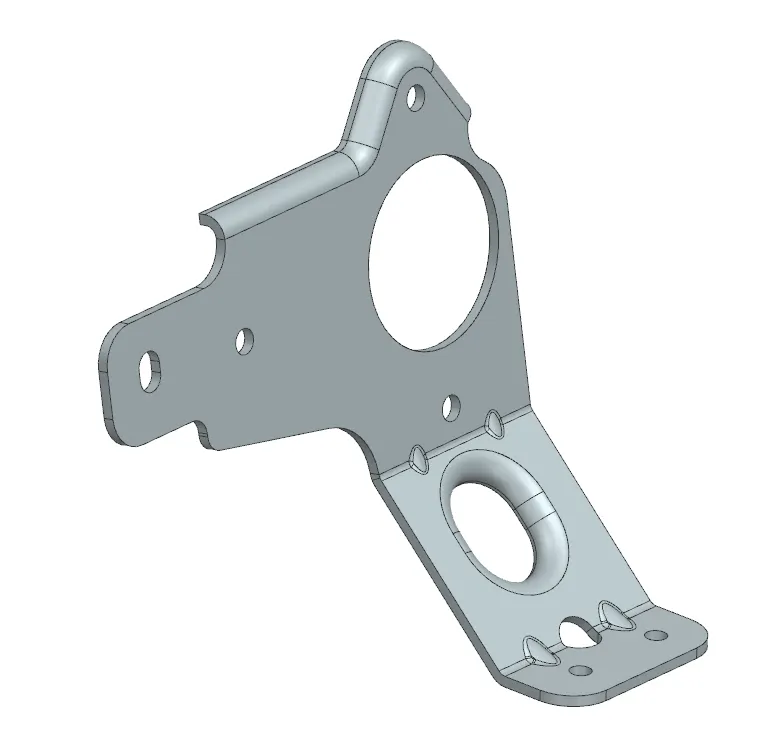
Metal Bracket
Introduction
In this project, we learn to Design Metal brackets using NX Cad for modeling. Siemens NX is a cutting-edge software that is highly useful for the manufacturing sector. It provides many applications like sheet modeling and modeling and drafting.
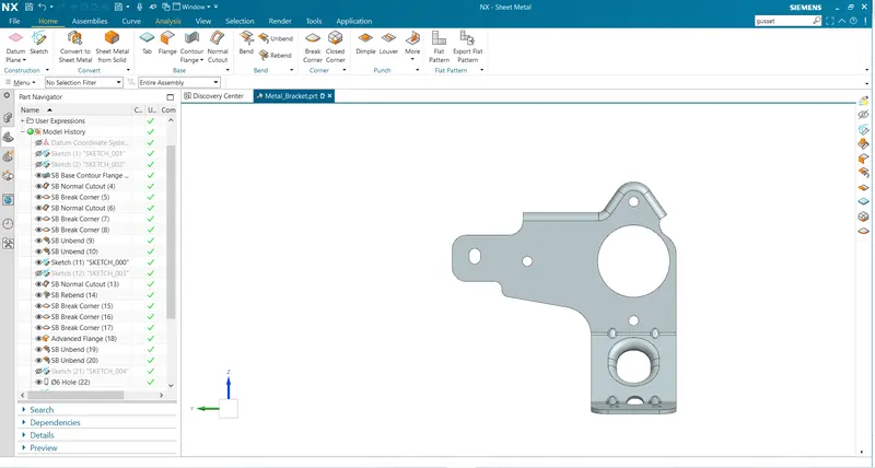
NX Sheet Metal contains a powerful set of tools to design and optimize sheet metal parts. Standard bending calculations, sheet metal features, and advanced analysis tools all contribute to improving quality and reducing the cost of sheet metal parts.
NX Sheet Metal provides a set of tools within the NX design environment that allows for simple and fast design of sheet metal parts, dependent on their material and manufacturing process, the most common of which is straight brake sheet metal forming.
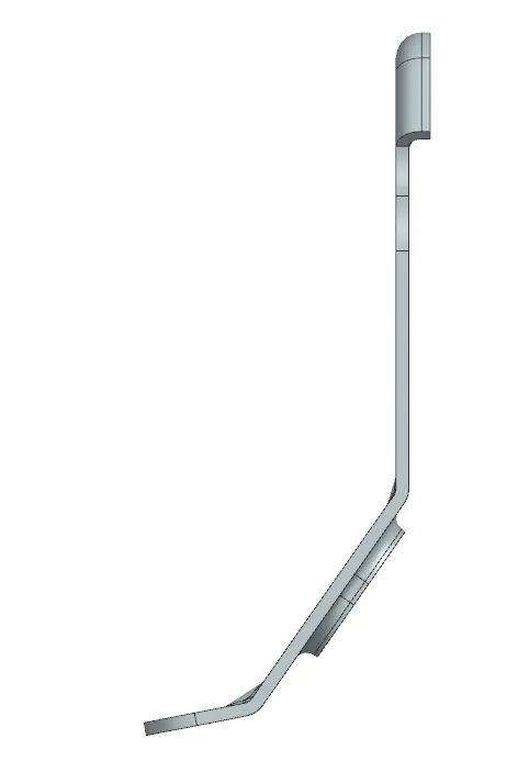
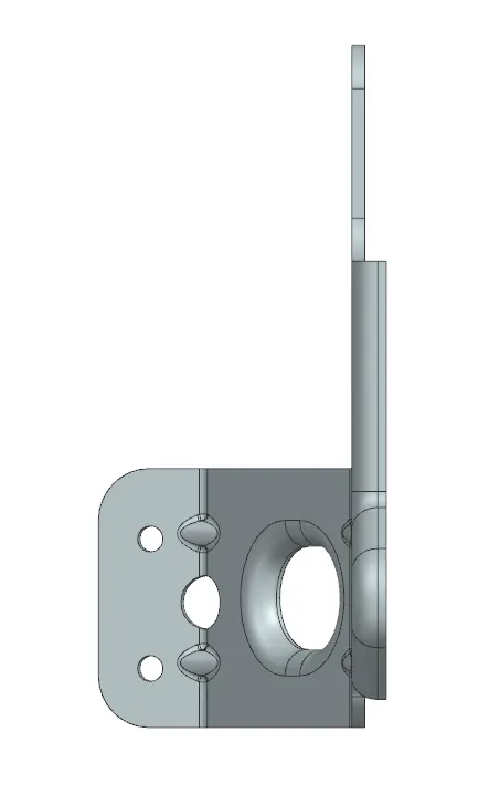
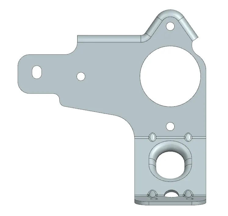
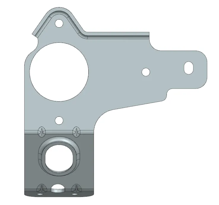
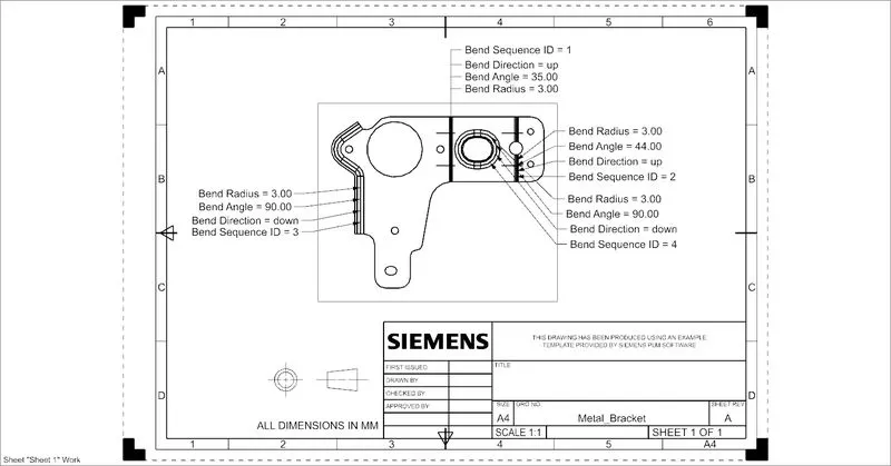
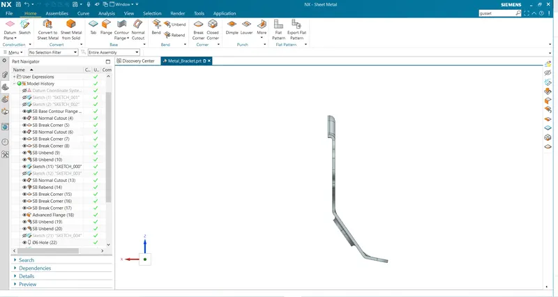
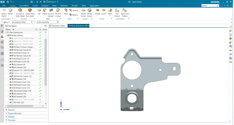
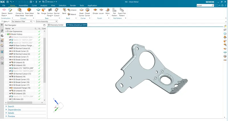
In Metal bracket Designing, NX sheet metal tools like Contour Flange, Normal Cutout, Hole, Unbend, Rebend, Gusset, etc to get the final model. The drafting tool is used to get the technical sketch of a Bracket made.
2.Tools / Features Used
- Contour Flange: It helps to create flanges from sketches of a particular thickness.
- Unbend: It helps to unfold the model surfaces and exhibit all surfaces to a plane. It flattens the bend.
- Normal Cutout: It helps to cut out material from the surface of the material.
- Hole: To create incisions on the surface based on the requirement. Closed sketches are made on the surface to create holes.
- Bead: Lifts material from the surface based on the sketch we provide. The sketch is stamped on the surface of sheet metal.
- Break Corner: It acts as a tool to fillet the corner edges. It can be also used to create chamfers too.
- Advanced Flanged: It helps to create flanges in curved edges.
- Gusset: It helps to add material at bends which stiff the sheet metal.
- Rebend: It helps to fold back the surfaces as they were. Bend and Rebend are the opposite tools that help in the unfolding and folding of surfaces.
- Flat pattern: Creates flat pattern features from formed sheet metal. Creating a flat solid allows the designer to quickly get a flattened model of the bent sheet metal part. This tool can be extremely useful to measure the total area of the sheet metal required for the component.
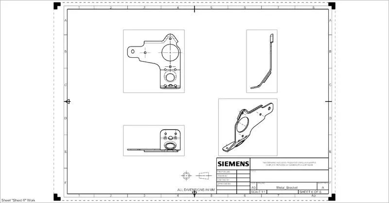
- Draft: After completing the final model drafting helps to get a technical drawing of the component at ratio.
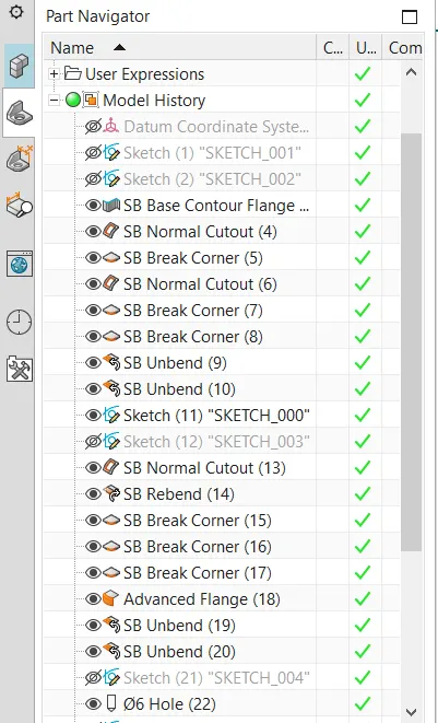
Design Process
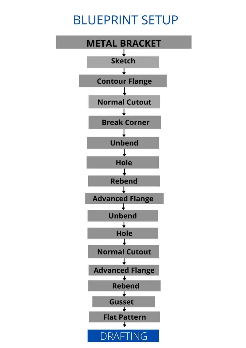
- Two sketches are made in the YZ and XZ planes.
- The sketch on the XZ plane is used to create a contour flange of a particular length.
- The Sketch on the YZ plane is used to cut out material from the contour flange.
- Break Corner is used to fillet the edges.
- The Sheet is unbent to create a hole at one of the ends.
- The sheet is rebent and then break corners are added to the outer edges.
- Advanced edges help to create flange on curved edges.
- It is again unbent to add holes on the surface of the sheet.
- Advanced Flange is added to one of the holes.
- The sheet is again rebent.
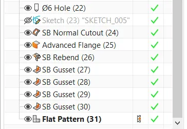
- Gussets are added at the bends of the sheet.
- A flat pattern is added to the end to flatten the sheet to one plane.
- Drafting is used to get technical sketches of the metal bracket made.