Advanced Sheet Metal Design Using NX Cad Challenge_7_ Metal bracket-II
METAL BRACKET
USING SHEETMETAL APPLICATION
INTRODUCTION
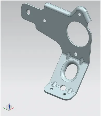
A detail description of stepwise sheet metal three dimensional model of the given two dimensional drawing using NX Sheet Metal Application. The metal bracket is designed as prescribed in the drawing and the parameters is taken under consideration.
DESIGN METHODOLOGY
DESCRIPTION
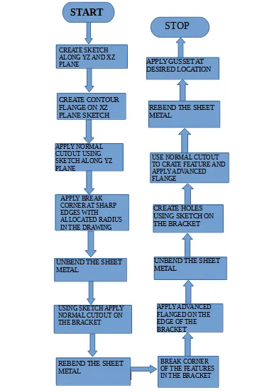
STEP 1:
Create a sketch on yz plane.
Step 2:
Create a sketch on xz plane.
Step 3:
Apply contour flange along xz plane sketch with thickness 3mm and width 158mm.
Step 4:
Use normal cutout with the previous sketch as a reference to get desired shape.
Step 5:
Apply Break corner along the sharp edges of the bracket with desired radius of 4.5mm, 4mm at different occasions.
Step 6:
Use normal cutout to create holes at desired locations for desired shape.
Step 7:
Apply break corner in these features with radius value of 4mm.
Step 8:
Create a circular sketch for generating a hole of diameter 12.5mm using normal cutout.
Step 9:
Rebend the metal bracket.
Step 10:
Apply break corners at other edges with radius value of 12mm, 5mm and 10mm.
Step 11:
Apply advanced flanged at one of the edges of the bracket with length 5mm.
Step 12:
Unbend the bracket.
Step 13:
Create hole at desired location using sketch with diameter 6mm.
Step 14:
Use Normal cutout to create new feature on the bracket.
Step 15:
Apply Advanced flanged on the edge of the feature with bend radius of 3mm and length 4mm.
Step 16:
Rebend the bracket.
Step 17:
Apply gusset with datum plane as the reference at a distance of 15mm from the corners. The depth of the gusset is 5mm, round form with width 8mm, side angle 45 degree and die radius 2.5mm.
SCREENSHOTS
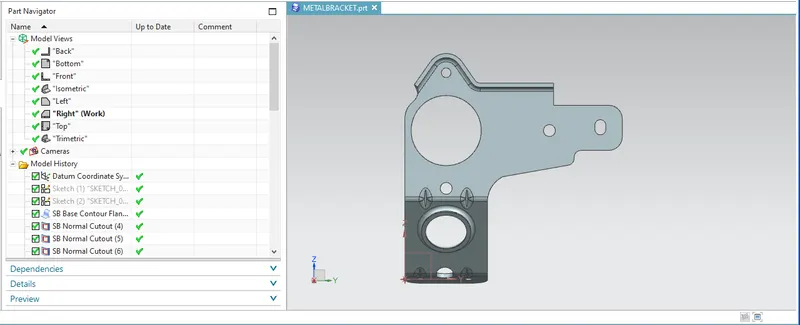
RIGHT VIEW
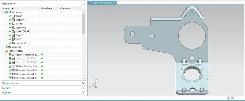
LEFT VIEW
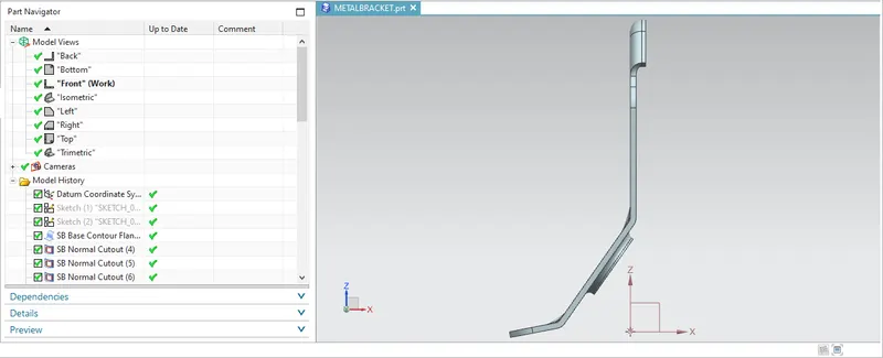
FRONT VIEW
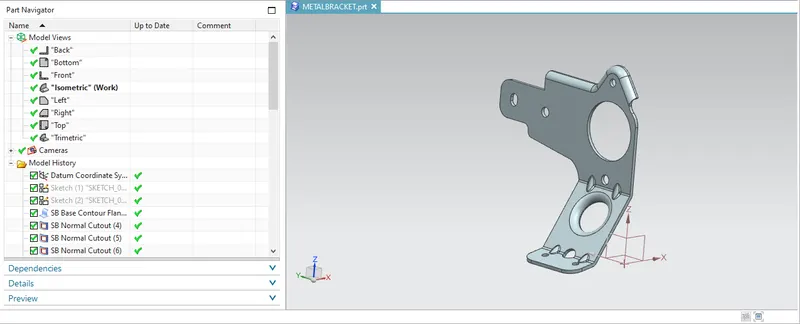
ISOMETRIC VIEW
CONCLUSION
This report covers in detail the design of the sheet metal drawing in Siemens NX Shhet metal application and highlights the main arrangement to cover the required steps to shape the desired model as described in the drawing.