Advanced Sheet Metal Design Using NX Cad Challenge_6_Bracket
BRACKET USING 2-D DRAWING
INTRODUCTION
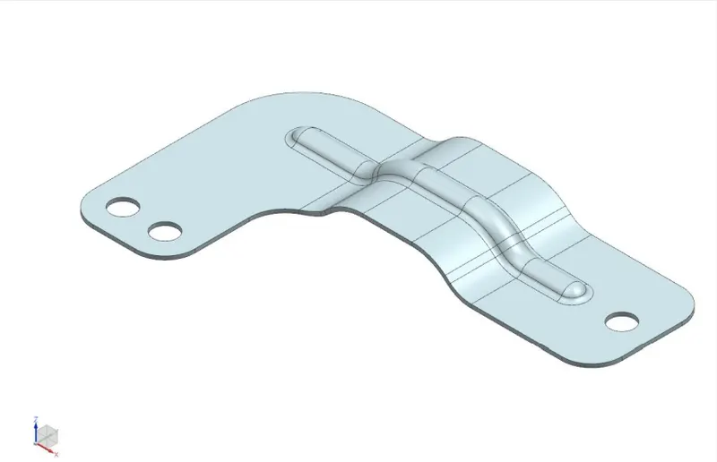
A two dimensional drawing is considered for creating a sheet metal design using NX Sheetmetal Application. The drawing mentions required parameters to design the bracket. This includes outline of a sketch and the dimensions of the features to be used in it. We will illustrate in detail about the necessary procedure to fulfil the expected three dimensional model in sheet metal application.
DESIGN METHODOLOGY
DESCRIPTION
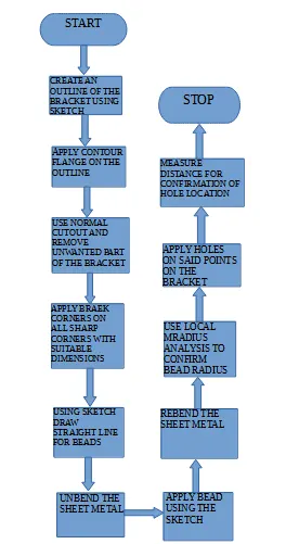
STEP 1:
Create a sketch as described in the drawing.
STEP 2:
Select the outline of the sketch drawn and apply Contour Flange to it. Provide thickness of 3mm and width 200mm.
STEP 3:
Apply Normal cut out for having a desired shape of the bracket. For this sketch the required shape with dimensions.
STEP 4:
Avoid sharp corners. These corners are replaced by blend radius for different corners with different parameters. Few with radius of 25mm others with 30mm and 60mm.
STEP 5:
Create a sketch on the plane where bead is suppose to be created as per drawing.
STEP 6:
Unbend the sheet metal to apply required features.
STEP 7:
Apply bead to the sketch previously drawn. Apply given parameters depth and radius on 7mm.
STEP 8:
Rebend the sheet metal.
STEP 9:
Apply holes at given points using given set dimensions and use hole command.
STEP 10:
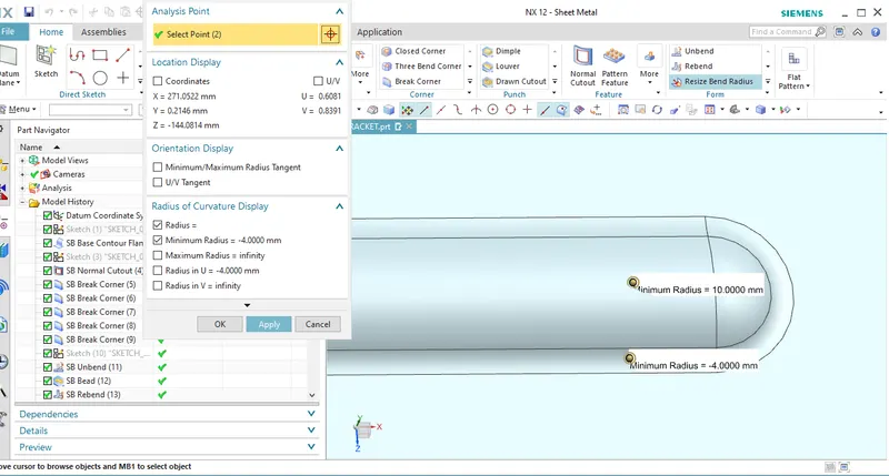
Check the radius of the bead using local radius analysis in the menu analysis section.
STEP 11:
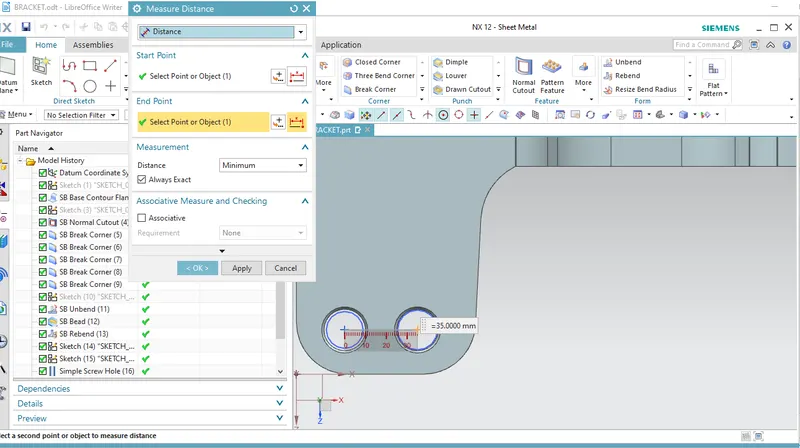
Measure distance using a measure distance command in the menu and analysis section. Confirm the distance of the hole.
SCREENSHOTS
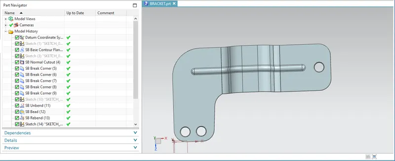
FRONT VIEW
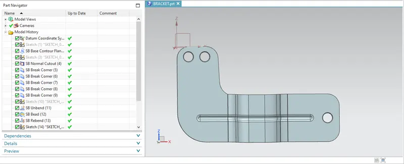
BACK VIEW
LOCAL RADIUS ANALYSIS
MEASUREMENT DISTANCE
CONCLUSION
The drawing of the given bracket is convert to a three dimensional sheet metal design using NX Siemens Seetmetal Application. This summarises the detail procedure of making the sheet metal model.