Advanced Sheet Metal Design Using NX Cad Challenge_5_Odd Shaped Enclosure
SHEETMETAL PART FOR ODD SHAPES
INTRODUCTION
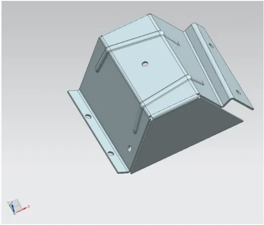
We will discuss the concerned workflow required to first modify a solid body to sheet metal and then use features from the Sheetmetal Application to generate desired shape for any sheet metal design.
DESIGN METHODOLOGY
DESCRIPTION
STEP 1:
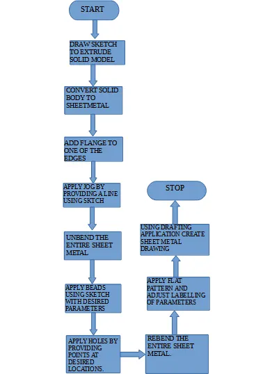
Draw a sketch to create a solid body.
STEP 2:
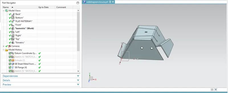
Apply Sheet Metal from solid and select web face along with all the bend edges of the solid body. Consider thickness parameters as 3mm and bend radius as 3mm.
STEP 3:
The solid body is now converted to sheet metal. Apply flange at one of the edges at the bottom. Consider length as 20mm right angle and length reference as inside along with Inset as Material Inside.
STEP 4:
Add jog to the sheet metal by sketching a line as a reference for the jog. Apply height of the jog to be 20mm with height reference as inside and inset as material inside.
STEP 5:
Before adding any other feature, unbend the sheet metal. Select the reference face and select the other faces to unbend the entire sheet metal.
STEP 6:
Sketch two straight lines on the flat unbend surface. Select these lines to create beads of depth 3mm and radius 3mm.
STEP 7:
Create select points using sketch to create holes of diameter 10mm with depth throughout the body.
STEP 8:
After finishing the features that needs to be applied on the sheet metal, rebend it by selecting all the faces and selecting one stationery face as a reference.
STEP 9:
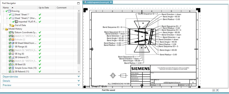
Create Flat Pattern and select face and edge for reference. On menu bar use sheet Metal Preference to select bend radius, bend angle, bend direction to denote the same on the flat pattern.
STEP 10:
Create draft Application and view the image on a standard A4 size paper.
SCREENSHOTS
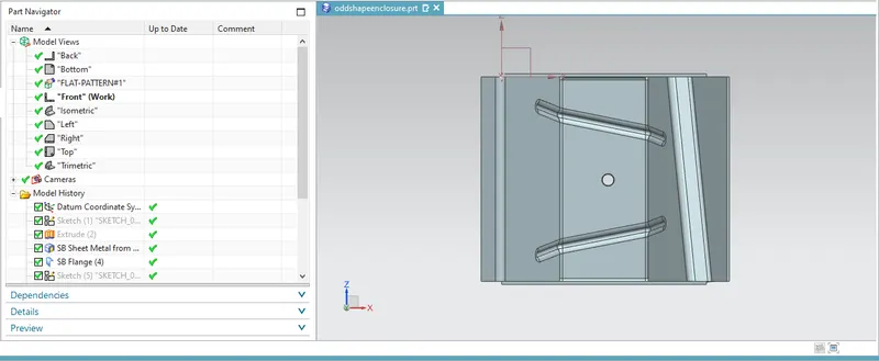
FRONT VIEW
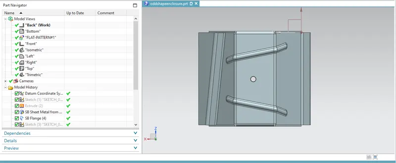
BACK VIEW
ISOMETRIC VIEW
DRAWING VIEW
CONCLUSION
In the above exercise we have illustrated the modification of solid body to sheet metal using NX Sheetmetal application and applied various features on the above sheet metal design.