Advanced Sheet Metal Design Using NX Cad Challenge_1_Casing Design
SHEETMETAL CASING USING SIEMENS NX SHEETMETAL APPLICATION
OBJECTIVE
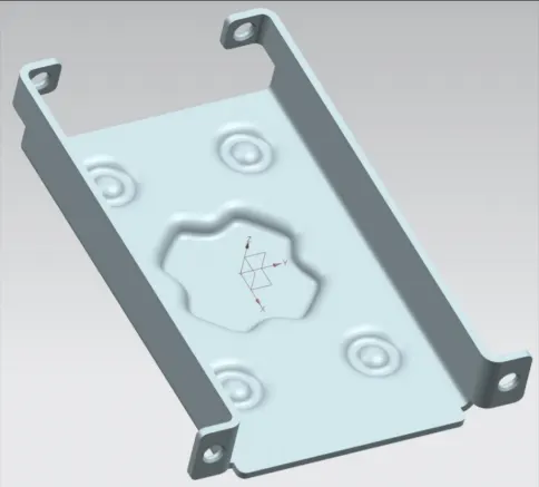
To design the given Sheet metal Casing using NX Siemens Sheetmetal Application with allocated dimensions and required features mentioned and create a detailed drawing of the same using drafting application.
INTRODUCTION
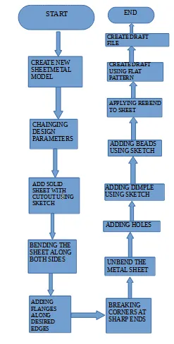
In this report we will discuss in detail about creating Sheet metal casing in Siemens NX Sheetmetal application. We will elaborate in detail stepwise approach using a flowchart in design methodology section with description of those steps in description section.
DESIGN METHODOLOGY
DESCRIPTION
-
Adding solid sheet with cut out
Using sketch, a rectangle shape tab is created with thickness 1mm. Creating a new sketch with a rectangle shape the unwanted sheet is cut out using Normal cutout command.
-
Bending
Two symmetric horizontal lines equally apart from center axis is used as a reference for bending. A 90 degree bend is created on both sides 10mm away from the corner edge of the sheet.
-
Adding flange
A flange 5mm length is applied on the edge of the bend surface. The direction of the flange is opposite in direction for the top two faces as against the bottom two faces.
-
Breaking corners
Using Break corner option all the sharp corners of the sheet metal are blend using radius of 1mm.
-
Unbending the metal sheet
Using Unbend option, the stationery face is selected as the reference and the faces are unbend by selecting individual adjacent faces.
-
Adding holes using sketch
By using sketch four points are created at four extremities of the sheet metal. This is done by creating a line at the extended part of the metal sheet and then selecting its centre points for hole. Using hole feature with screw clearance hole as type and M2 screw size with H13 fit the points are selected for crating hole feature.
-
Adding a dimple using sketch
By sketching a plus shape pattern and adding studio spline option a desired pattern is created. Using Dimple option the sketch is selected with depth of 1mm and side wall selected as Material inside.
-
Adding beads
Four different circles are sketched at the desired location using different corners for dimensional reference. Bead feature is used in this case with depth and radius of 1mm and cross section to circular.
-
Rebend
Using the rebend command all the adjacent bends that were unbend earlier is rebend again.
-
Drafting using Flat pattern
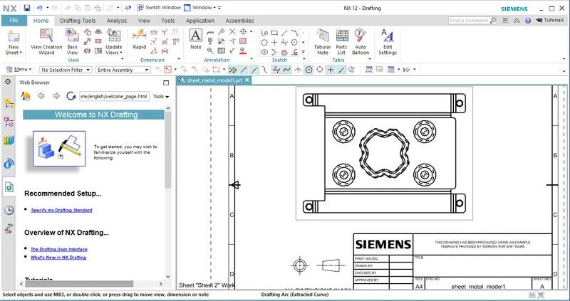
Drafting of the model is created using Flat pattern feature. A drafting file is created with size A4 with a scale of 2:1.
SCREENSHOTS OF FINAL MODEL
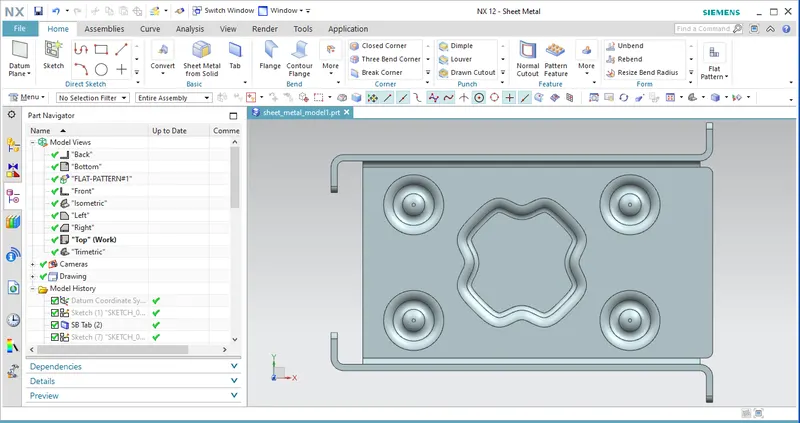
TOP VIEW
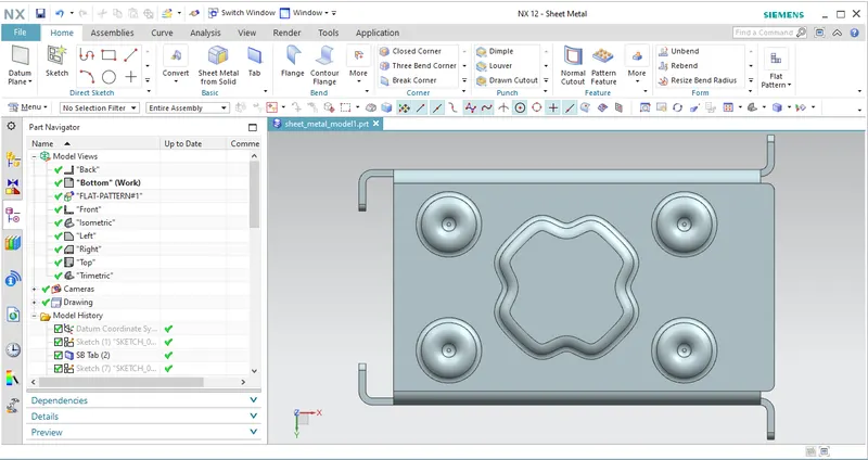
BOTTOM VIEW
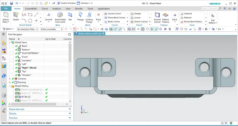
RIGHT VIEW
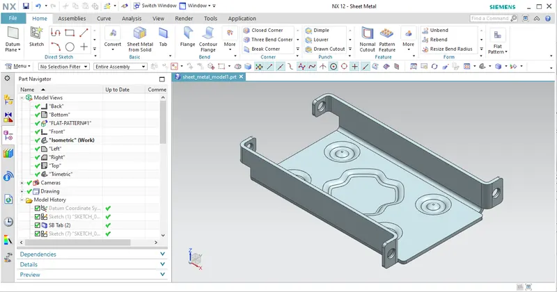
ISOMETRIC VIEW
DETAILED DRAWING SHEET IMAGE
CONCLUSION
In this report we have explained in detail about creating sheet metal casing model using Sheetmetal application. We have described the stepwise approach to generate desired feature on the sheet metal and also created drawing using drafting application.