Sheet Metal Bracket II Design using NX CAD
Sheet Metal Bracket II Design using NX CAD
Objective:
To learn and design of sheet metal bracket II using NX CAD.
Introduction:
Sheet Metal
The sheet metal parts can be found from the small light fixtures to the automotive body parts because of their high strength despite having low weight and its resistance to corrosion. Based on the requirements and the standards sheet metals of varying thickness are used.
The sheet metal comes from various materials such as steel, aluminium, brass, titanium and more.
Bracket
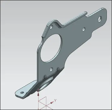
There different types of bracket design. These are manufactured by conducting stamping or die casting operation. Bracket is use for mounting purpose in different assembly or sub-assembly. Bracket is provided with different shapes and features to increase strength. This project explain bracket designing procedure using NX CAD sheet metal workbench.
Design Methodology
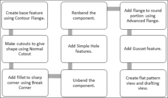
Description
Tools Used
- Contour Flange: - It creates a base feature by extruding a sketch along a vector or adds material by sweeping a sketch along edge or chain of edges.
- Normal Cut-out: - It cuts material by projecting a sketch onto the model and then cutting perpendicular to the faces intersected by the projection.
- Break Corner: - It rounds and chamfers a sharp corner of a tab or flange.
- Advanced Flange: - Adds a flange along an edge using a bend angle or a reference face. The edge and reference face can be curved.
- Unbend: - This tool flattens the bend and the material adjacent to the bend.
- Simple Hole: - It add hole to one or more solid bodies in part or assembly.
- Rebend: - It restores an unbend feature to its previous bent state, along with any features added after the unbend feature.
- Gusset: - Creates a stiffening gusset on the part.
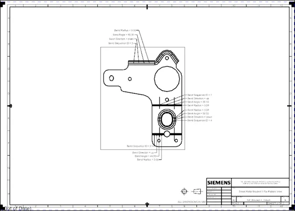
- Flat Pattern: - This tool creates flat pattern of form sheet metal part. It explained about component manufacturing information.
Procedure to create bracket II explained as below
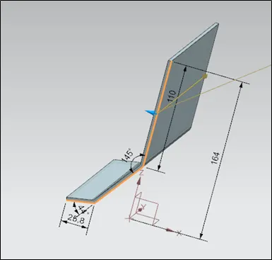
1. Contour Flange
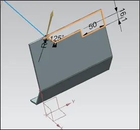
2. Normal Cut-out
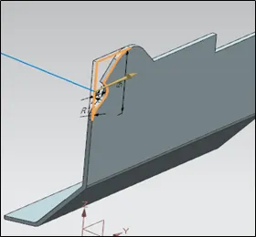
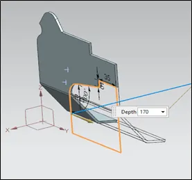
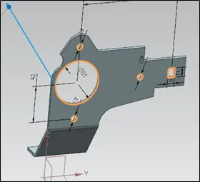
3. Unbend and Normal Cutout
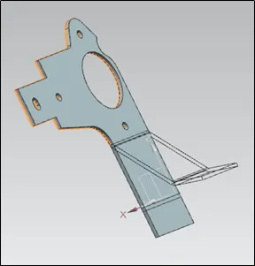
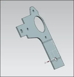
4. Rebend
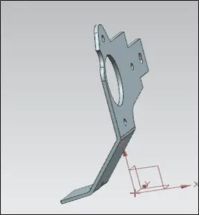
5. Break Corner
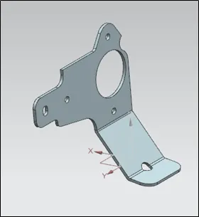
6. Advanced Flange
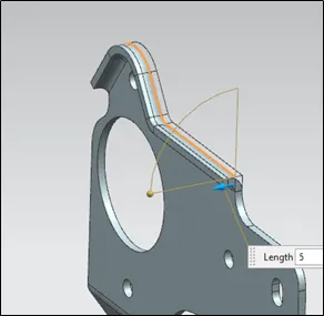
7. Unbend and Normal Cutout
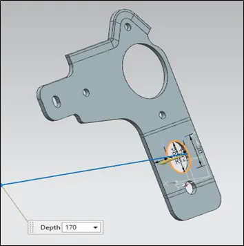
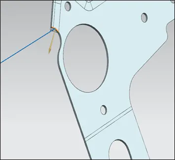
8. Rebend and Advanced Flange
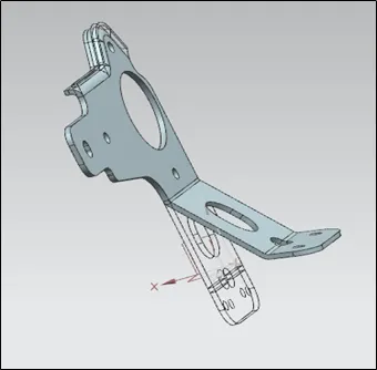
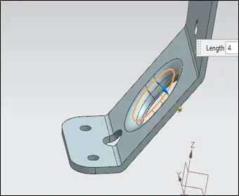
9. Gusset
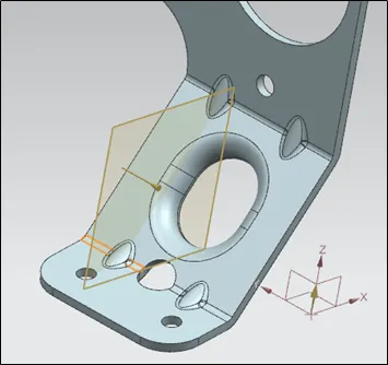
10. Flat Pattern
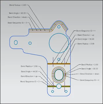
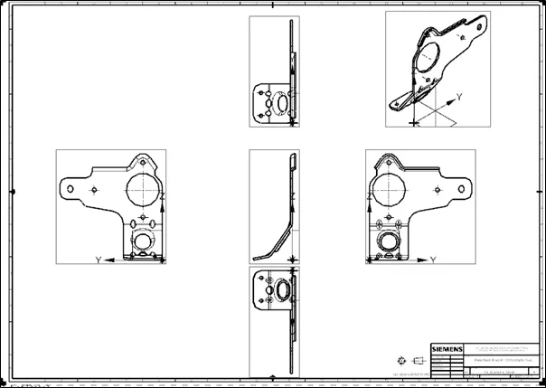
Different View: -
a) Front Side
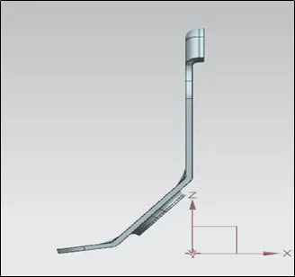
b) Top Side
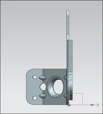
c) Right Side
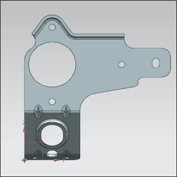
d) Isometric View
Drafting of Sheet Metal Box Assembly
a) Sheet Metal Box Assembly Flat Pattern View
b) Sheet Metal Box Assembly Orthographic View
Conclusion
Designing and drafting of sheet metal bracket II done using NX CAD workbench.