Sheet Metal Box Assembly Design using NX CAD
Sheet Metal Box Assembly Design using NX CAD
Objective:
- To get user interface with NX CAD Sheetmetal Workbench.
- To design and drafting of a sheet metal Box Assembly in sheet metal workbench using NX CAD.
Introduction:
Sheet Metal
The sheet metal parts can be found from the small light fixtures to the automotive body parts because of their high strength despite having low weight and its resistance to corrosion. Based on the requirements and the standards sheet metals of varying thickness are used.
The sheet metal comes from various materials such as steel, aluminium, brass, titanium and more.
Sheet metal is metal formed by an industrial process into thin, flat pieces. Sheet metal is one of the fundamental forms used in metalworking, and it can be cut and bent into a variety of shapes. Countless everyday objects are fabricated from sheet metal. Thicknesses can vary significantly; extremely thin sheets are considered foil or leaf, and pieces thicker than 6 mm (0.25 in) are considered plate steel or "structural steel".
Design Methodology
Description
In this project, box assembly design and drafting is done using NX CAD Sheetmetal workbench.
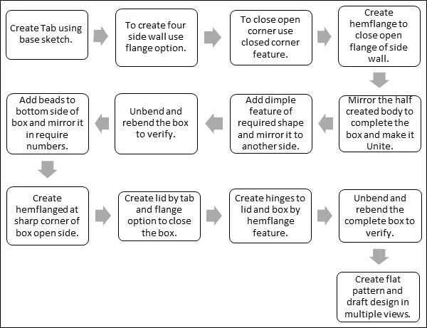
To create box assembly in NX CAD following feature and process is followed.
Box Assembly
Box can be made from different material with different processes. In this project, I have learned how to design and draft box assembly by using NX CAD sheet metal workbench.
To design box assembly sheet metal used as a material.
Component of Box Assembly.
- Box (Top side opened)
- Box Lid
- Hinge
A. Box
1. Base: - It is base feature is used to create any sheet metal component. It creates base feature by extruding sketch along a vector by thickness value or add material to planner face.
In this model, a rectangle sketch drawn of 200mm*150mm size and tab it to get sheet of 1 mm.
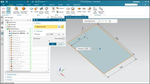
2. Side Wall: Side wall of box created by using flange feature.
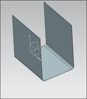
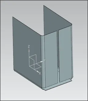
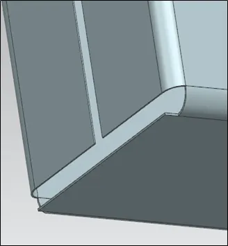
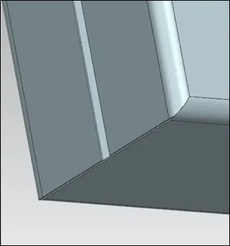
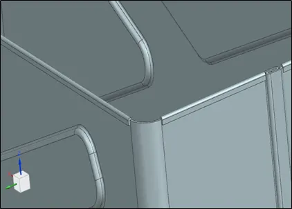
3. Closed Corner: This feature allows to closed corner of extended flanges to remove sharp corners and provide smoothening ends.
Closed corner feature used while designing box assembly as shown in pic.
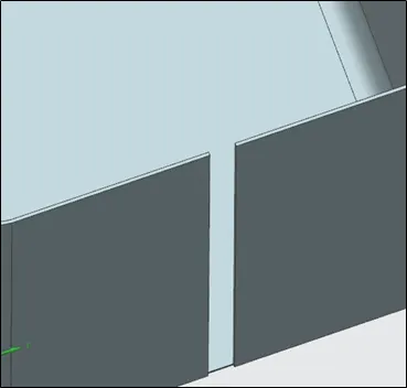
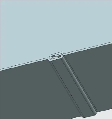
4. Hem Flange: - Closed loop hem flange created at side wall to close the gap between flanges of side wall
5. Mirror Body: This option is use to complete box by mirroring half body along a plane.
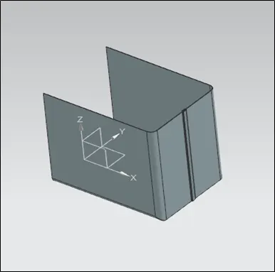
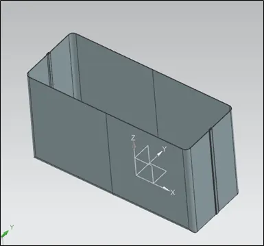
6. Unite: - It combines volume of two or more solid bodies into a single body. It is use after use of mirror body option.
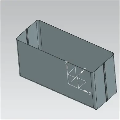
7. Dimple: - It lifts an area of the model inside a sketch that simulates a stamping tool.
In box assembly design, draw sketch as shown in picture and use same sketch to create dimple feature. Mirror the dimple feature to the other side wall of a box by mirror feature option.
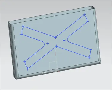
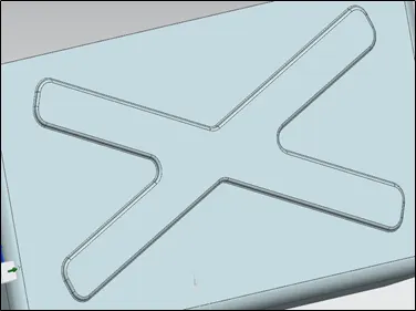
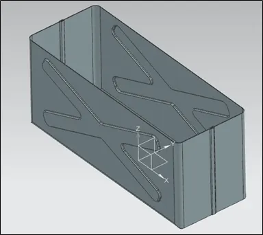
Again, dimple feature created at bottom side of box
8. Bead: - It lift material along the counter of a sketch that simulates a stamping tool.
To create draw a sketch and use same sketch to create bead feature. This feature is mirrored as shown in pic.
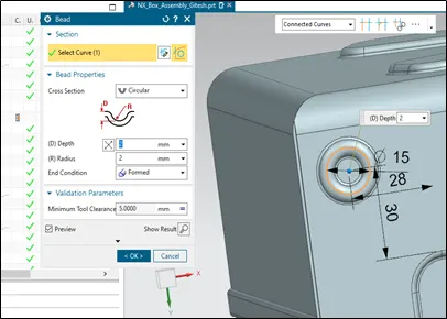
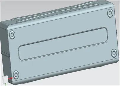
9. Hem Flange: - Hem flange is created at sharp corner of box side wall.
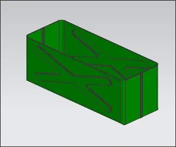
Final box completed.
B. Box Lid
1. Datum Plane: - Datum plane with respect to XY plane of datum coordinate system to an offset of 203 mm.
2. Sketch and Tab: - Create sketch on new plane for box lid. Create lid using tab tool using same sketch.
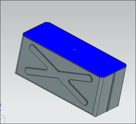
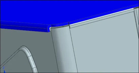
3. Flange: - Flange added to three edges of lid to complete the box lid.
C. Hinge
1. Tab: - Create tab as a base for hinge support as shown pic.
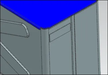
2. Break Corner: - It add chamfer or fillets to sharp edges.
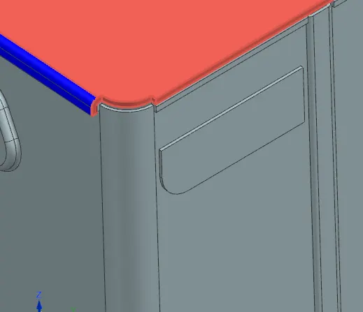
3. Flanges and Hem Flange: - Add flange to base tab to add hem flange at some distance from side wall.
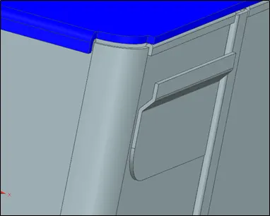
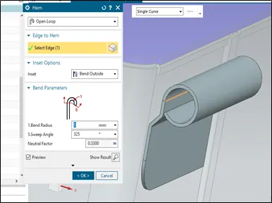
4. Unbend, Normal Cut-out and Rebend: - To make cut-out in flanges, first need to unbend the flanges. Draw a sketch of require cut-out and make cut-out. Rebend the flanges again.
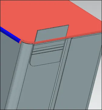
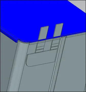
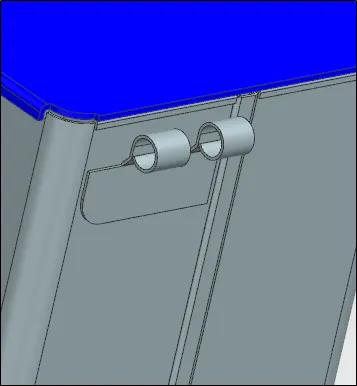
5. Mirror Body: - Use mirror body option to mirror hinge along a XZ plane.
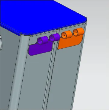
6. Hinge on Lid Side: - Repeat same procedure to create hinge on lid side as it can guide to box hinge.
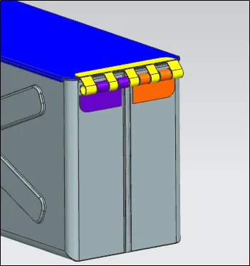
Box Assembly completed.
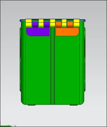
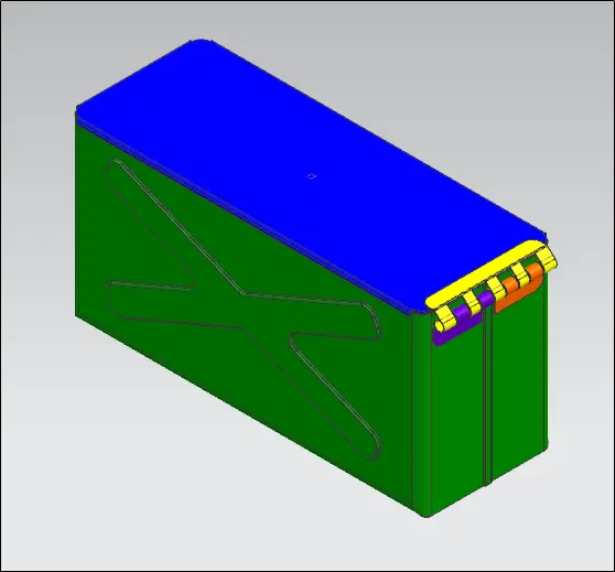
Different view of Sheet Metal Box Assembly
a) Front View
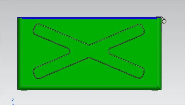
b) Bottom View
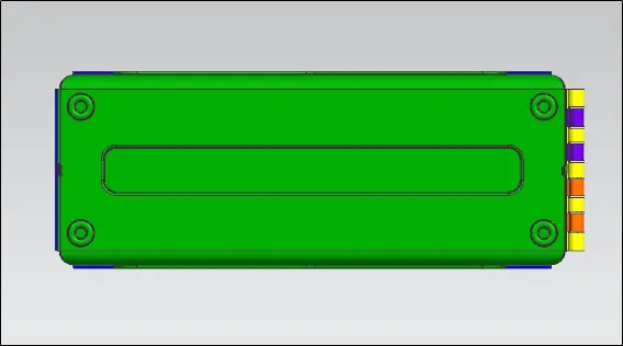
c) Left View
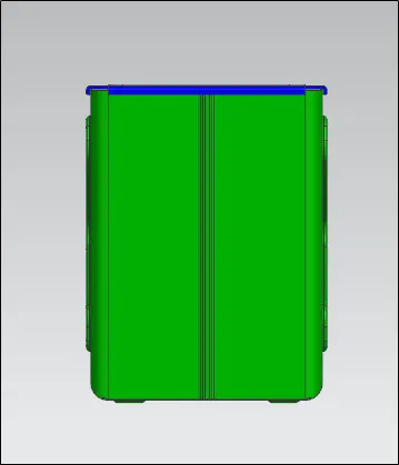
d) Right View
f) Isometric View
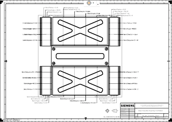
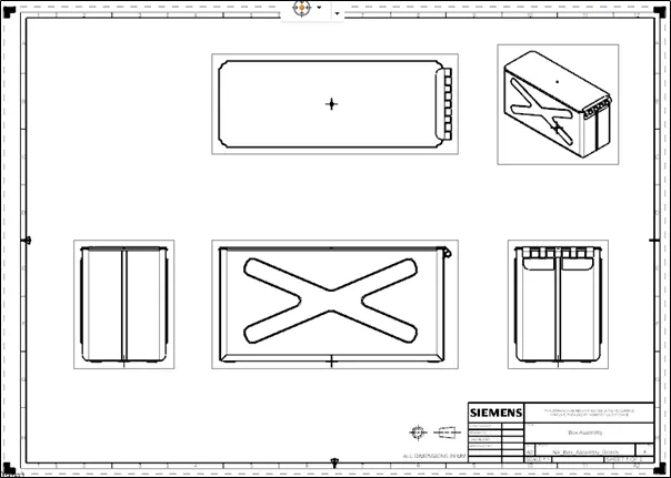
Drafting of Sheet Metal Box Assembly
a) Sheet Metal Box Assembly Flat Pattern View
b) Sheet Metal Box Assembly Orthographic View
Conclusion
- Understand about user interface with NX CAD Sheetmetal Workbench.
- Sheet metal Box Assembly design and drafting completed using NX CAD Sheetmetal Workbench.