Sheet Metal Casing Design using NX CAD
Sheet Metal Casing Design using NX CAD
Objective:
- To get user interface with NX CAD Sheetmetal Workbench.
- To learn about sheet metal component manufacturing approach.
- To design and drafting of a sheet metal casing in sheet metal workbench using NX CAD.
Introduction:
Sheet Metal
The sheet metal parts can be found from the small light fixtures to the automotive body parts because of their high strength despite having low weight and its resistance to corrosion. Based on the requirements and the standards sheet metals of varying thickness are used. The sheet metal comes from various materials such as steel, aluminium, brass, titanium and more.
Sheet metal is metal formed by an industrial process into thin, flat pieces. Sheet metal is one of the fundamental forms used in metalworking, and it can be cut and bent into a variety of shapes. Countless everyday objects are fabricated from sheet metal. Thicknesses can vary significantly; extremely thin sheets are considered foil or leaf, and pieces thicker than 6 mm (0.25 in) are considered plate steel or "structural steel".
Application of Sheet Metal
- Aircraft Bodies
- Automobiles Bodies
- Utensils used for Domestic Purpose
- Beverage Cans
NX CAD Sheetmetal
NX sheet metal design software incorporates material and process information in sheet metal- specific modelling features: bends, flanges, tabs, cut-outs, beads, dimples, louvers, corner and edge treatments, patterns and other formable features. You can also quickly convert solid models to sheet metal components, and create sheet metal parts that enclose other components.
NX Sheet Metal specific features such as flanges, tabs, jogs, corner conditions, and drawn cut-outs & many more along with productivity enhancements such as automatic bend reliefs.
The software also provides common modelling features typically used in sheet metal design, such as holes and slots, as well as other essential capabilities such as copy, paste, and mirror.
The application provides defaults for sheet metal specific properties such as material thickness, bend radius, and bend relief. You can easily change these defaults.
Sheet Metal Terminology
Bend Radius: The sheet metal is bent to the required angle by the press brakes. The press brakes which bend the sheet metal do not provide a 90-degree corner, instead it will have curved corners. The radius of the inside curve is called the Bend radius.
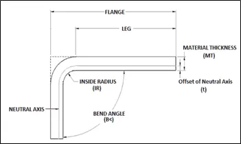
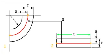
K-Factor: When a material is bent, the inner portion undergoes compression and the outer portion gets stretched, which means the inner length of the bent material decreases and the outer length of the material increases. In between them there is a line called ‘neutral line’ where there is no change in length and this is where the transition of compression to tension takes place.
The ratio of the neutral line distance to the material thickness is called “K-Factor”. The value K-Factor depends on material thickness, material properties and the bend radius.
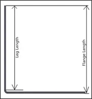
Bend Allowance: The bend allowance is defined as the material added to the leg length of the sheet metal to produce a flat pattern.
Design Methodology
Description
In this project, casing design and drafting is done using NX CAD Sheetmetal workbench.
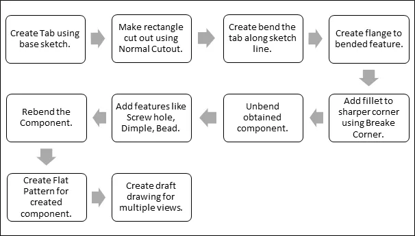
To create casing in NX CAD following feature and process is followed.
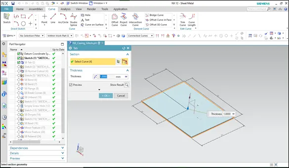
- Tab: - It is base feature is used to create any sheet metal component. It creates base feature by extruding sketch along a vector by thickness value or add material to planner face.
In this model, a rectangle sketch drawn of 60mm*50mm size and tab it to get sheet of 1 mm.
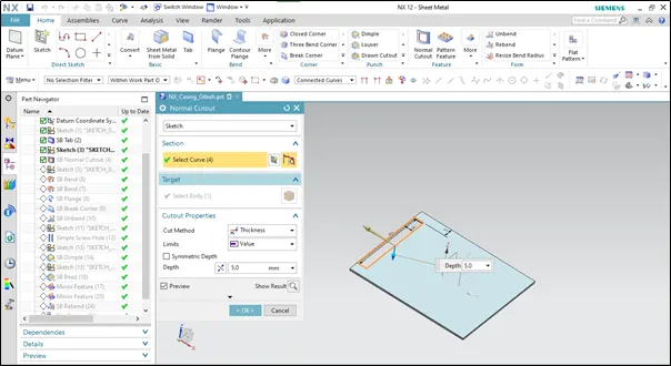
- Normal Cut-Out: - It cut the material by projecting drawn sketch on to the model and cutting perpendicular to the faces intersected by the projection.
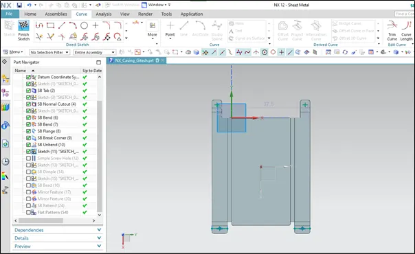
After tabbing, normal cut-out feature is used to cut sheet by 40mm*5mm size as shown in below picture.
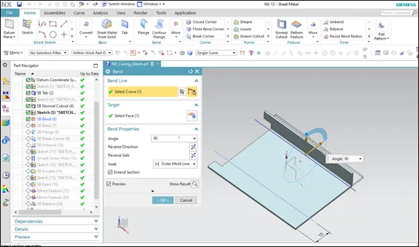
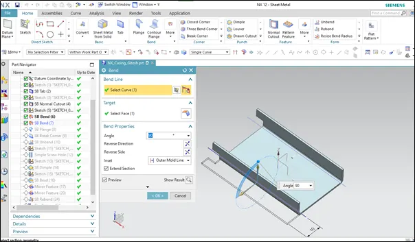
- Bend: This feature allows to bend sheet along a sketch line. It provides flexibility to bend the sheet by different angle, length and directions as per requirement.
Bend feature perform in casing design as shown in picture.
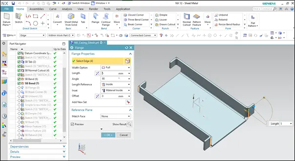
- Flange: - It adds a flat flange at an angle to a planner face and bends between two. It actually adds bend the bent portion of sheet. In casing design, to add flange select the four edges of bent portion of sheet. Selection of edges depend upon direction of flange required.
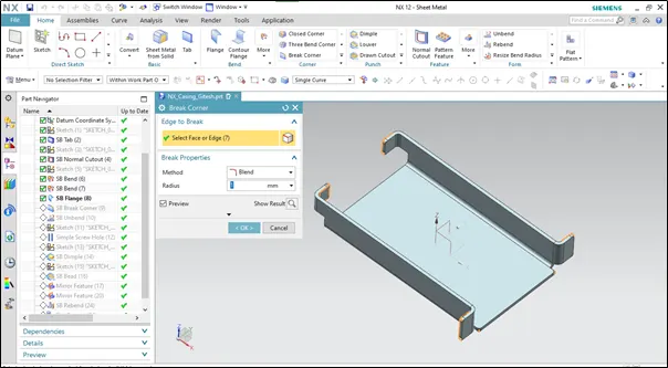
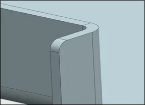
- Break Corner: - It used to apply fillet and chamfer to sharp corner of a tab or flange.
In casing design, sharp corner or adjacent faces to be select for rounding and required radius value to be input.
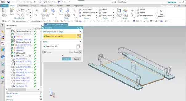
- Unbend: - It flattens a bend and the material adjacent to the bend. It is required to unbend the component to add additional feature like Dimple, bead. In this option, first need to select base (stationary face or edge) and then select bent portion to unbend.
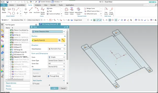
- Hole: - It is used to add a hole one or more hole to solid bodies in part or assembly with options for counterbored, countersunk and threaded.
In casing design, sketch four point on face. Specify four point and select appropriate options like direction, form, depth limit and start-end chamfer.
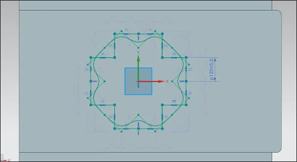
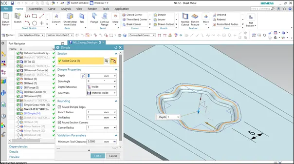
- Dimple: - It lifts an area of the model inside a sketch that simulates a stamping tool.
In casing design, draw sketch as shown in picture and use same sketch to create dimple feature.
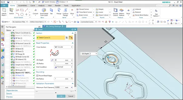
- Bead: - It lift material along the counter of a sketch that simulates a stamping tool.
In casing design, draw a circle and create bead feature.
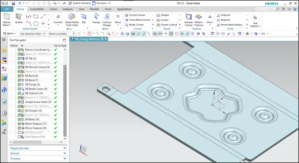
- Mirror Feature: - This feature use to copies a feature and mirror it across a plane.
In casing design, three bead features mirrored across a plane.
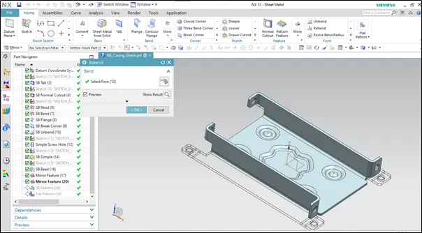
- Rebend: - It restores an unbend feature to its previous bent state, along with any features added after the unbend feature.
To rebend the component, select all bent features.
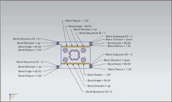
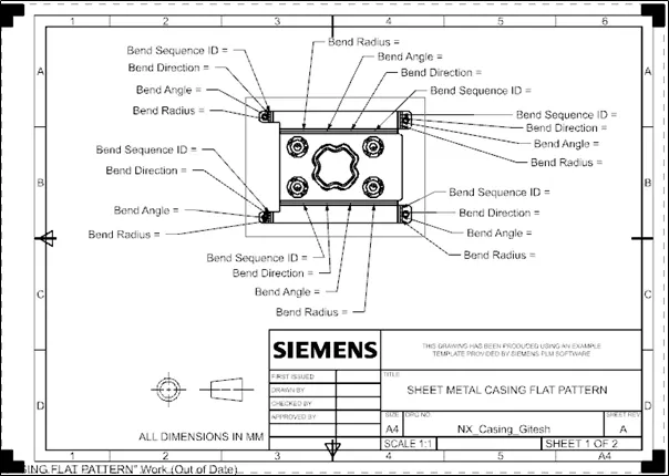
- Flat Pattern: - It creates a flat pattern feature from the formed sheet metal part. It is the representation of entire sheet metal component in 2D form. It show information about features added to component which is needed to manufacture the component.
- Drafting: - It used to create 2D drawing from a 3D model. It refers to technical drawing that communicate about dimensions, view of geometry and additional features that perform on part in 2D or 3D. The draft drawing show relations, annotation and dimensions which help in manufacturing the component.
Following draft drawing prepared for Sheet Metal Casing.
a) Sheet Metal Casing Flat Pattern View
b) Sheet Metal Casing Orthographic View
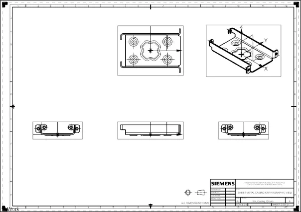
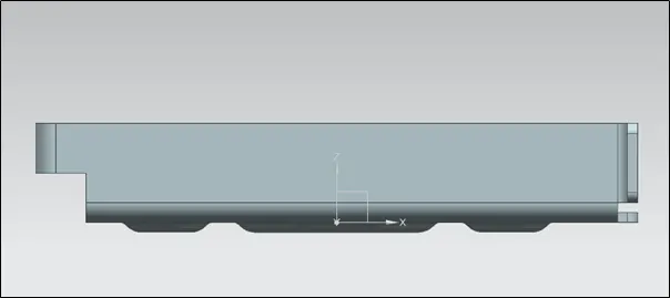
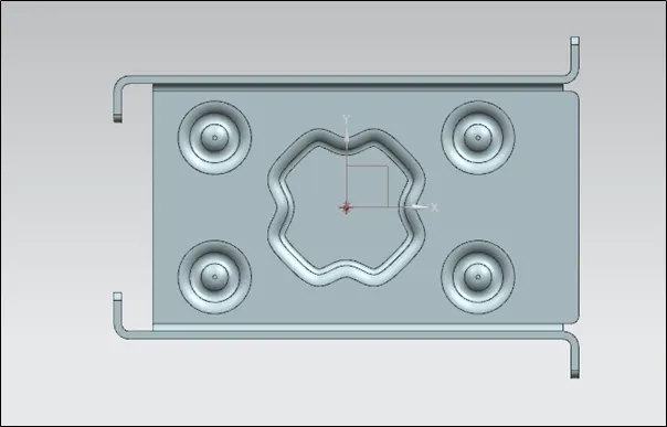
Different view of Sheet Metal Casing
a) Front View
b) Top View
c) Bottom View
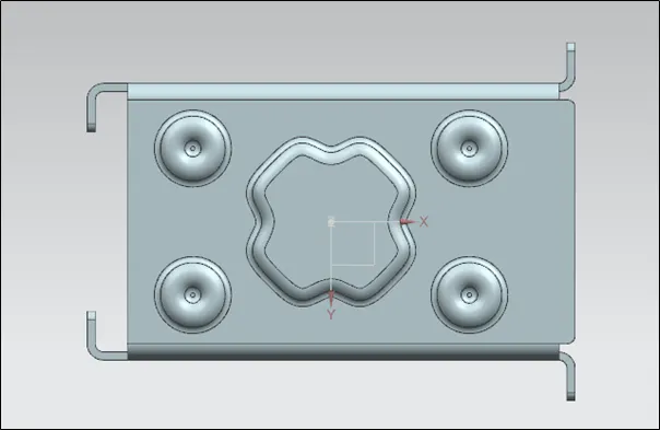
d) Left View
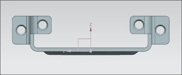
e) Isometric View
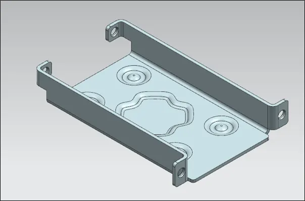
Conclusion
- Understand about user interface with NX CAD Sheetmetal Workbench.
- Learned about sheet metal component manufacturing approach.
- Sheet metal casing design and drafting completed using NX CAD Sheetmetal Workbench.
- Learned basic commands of NX CAD Sheetmetal Workbench.