Advanced Sheet Metal Design Using NX Cad Challenge_7_ Metal bracket-II
DESIGNING OF BRACKET SHEET METAL PART 2 USING NX SHEETMETAL APPLICATION
OBJECTIVE:
Main objective is to Designing a Bracket using NX sheet metal application and also to explain the tool used in this NX sheet metal application.
INTRODUCTION:
The project is about to Designing Bracket and explaining the tools used in the NX Sheetmetal application to create the sheet metal part.
A Bracket is a Sheetmetal component which act as an intermediate component for fixing one part to another, this intermediate between the two and fixes the one to the other. This project consists of features like Contour flanges, Normal cut out, hole and Gusset. Every feature is designed in an order following the industrial procedure to keep the design intent.
DESIGNING METHODOLOGY:
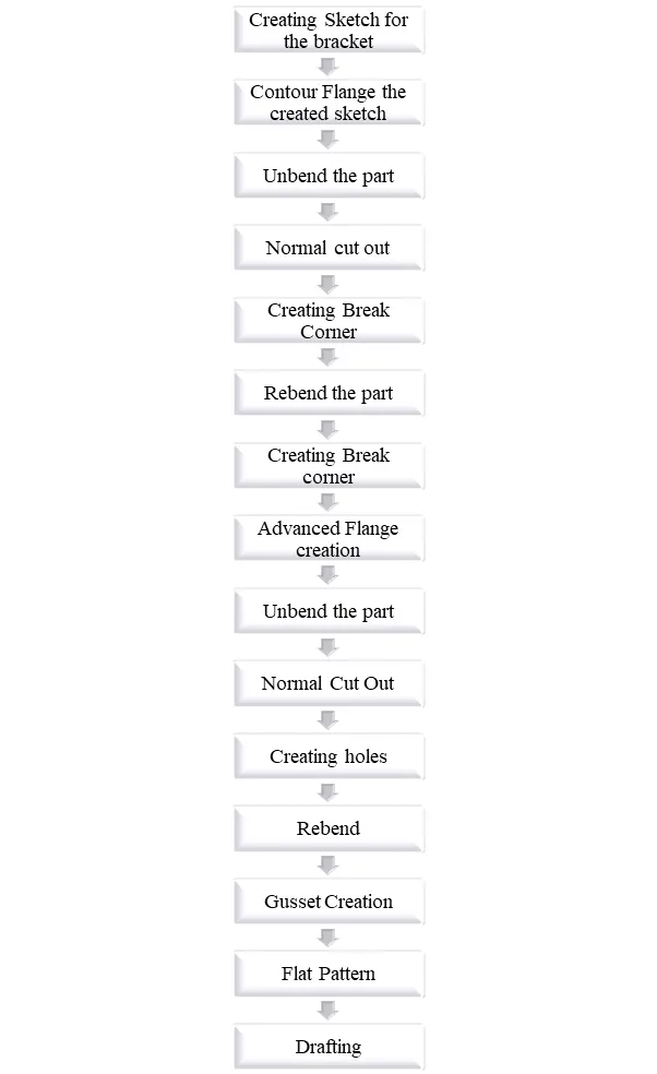
The designing methodology of Bracket model are been done following steps which are been shown in the form of flow chart.
DESCRIPTION:
SKETCHING OF BRACKET SHEET METAL PART:
The sketch is the fundamental base element for any model which is to be designed in sheet metal application. Each and every model required a sketch to carry on further in their modelling process.
The sketch is the basic requirement to create any kind features to be in the NX Sheetmetal application so the first sketch created is called as base sketch. The sketch can be created according to design requirements.
CONTOUR FLANGE:
The Contour Flange is a base feature by extruding a sketch along a vector or adds material by sweeping a sketch along an edge or chain of edges. In this project the Contour Flange acts as the main feature which extrudes the sketch created according to design requirement.
NORMAL CUTOUT:
Normal Cut Out is necessary to remove material from a sheet metal part, you must use the Normal Cut out command in order to remove specific area to achieve design progress according to the designing methodology.
BREAK CORNER:
The break corner feature breaks the sharp edges in the corners and makes it round or adds chamfer. It is like fillet feature which prevents fracture breaking in the sharp corners.
UNBEND:
The unbend is a very useful tool in sheet metal application it allows all the bent made by the bent and flange feature tool. To achieve a unbend need to select the bended face by this the bended area can be converted into unbend model.
HOLE:
Hole feature creates hole on the sheet metal. The hole feature also can create either simple or counter bore or countersink or tapped holes. In this model the four points are selected for creating holes symmetric to the x axis.
REBEND:
All the features added after the unbend feature are added in the unbend state. After the addition of sketches and additional features are completed. The sheet metal component has to be rebend to required position. This is done using the rebend feature and selecting all the bends in order or by Bracket selection. This completes the design process of the Bracket adding the feature.
ADVANCED FLANGE:
The Advanced Flange is a process of adding a flange along an edge using a bend angle or a reference face. The edge and reference face can be curved.
GUSSET:
The Gusset is the process of creating a stiffening on the part by selecting face and plane assigning. The gusset provides stiffness to the part by assigning depth of the gusset and also width, side angle, die radius.
FLAT PATTERN:
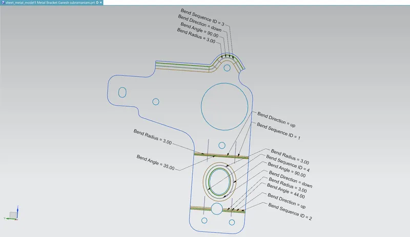
Flat pattern is the representation of the entire sheet metal component in the 2D form of the flat sheet metal with all bends, cut outs, holes and additional features. The Flat pattern ensures the ability to cut the sheet metal out of raw sheet metal plane it removes the possible errors such as interference or collision within the same component.
DRAFTING:
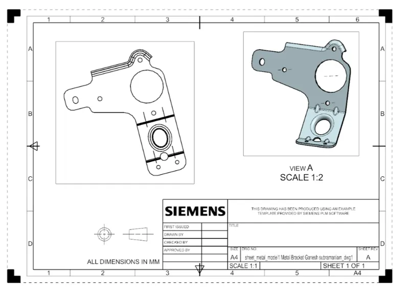
After the design is complete the execution or the manufacturing of the component required a technical drawing of the component with the provided scale and with accuracy. The necessary details such as annotations callouts bend table can be added as per the requirements. For this Bracket design a drawing is created out of the flat pattern in a 2:1 scale in A4 size.
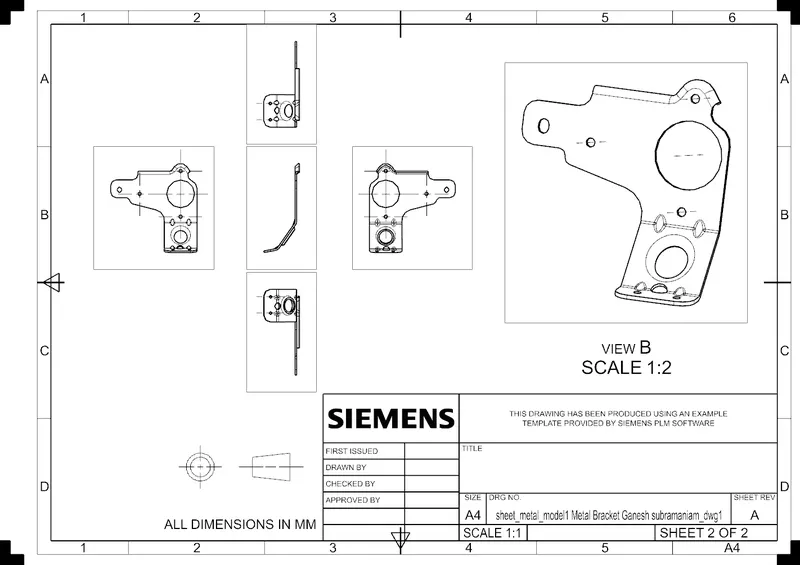
DIFFERENT VIEWS OF COPLETE DESIGN OF SHEET METAL BRACKET:
ISOMETRIC VIEW:
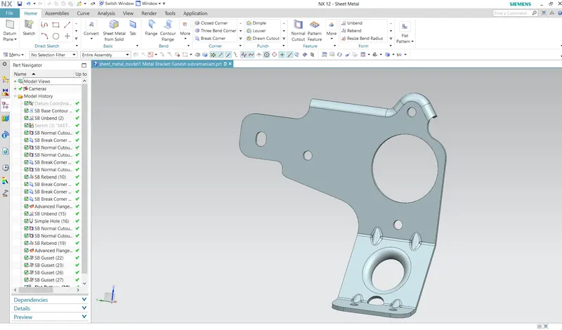
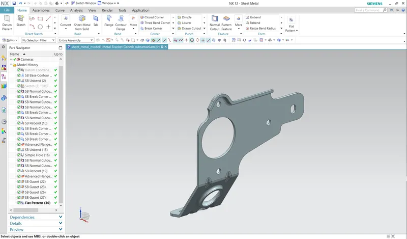
FRONT VIEW:
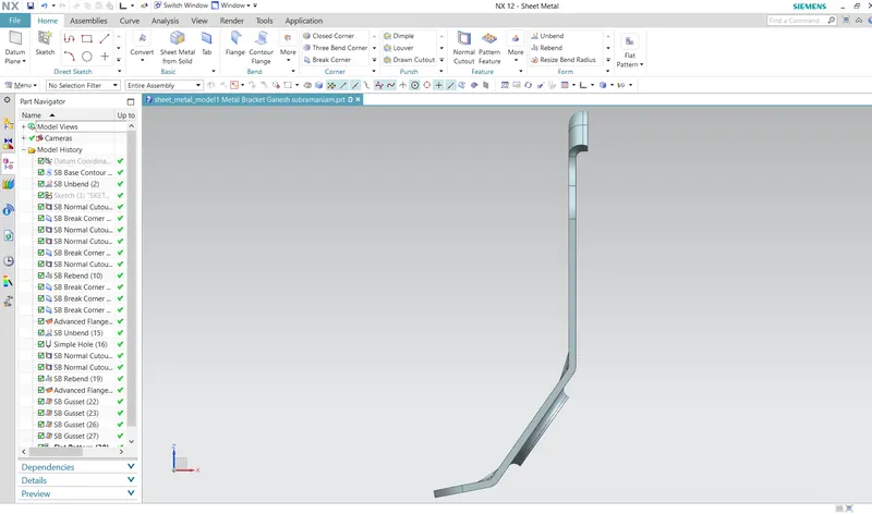
SIDE VIEW:
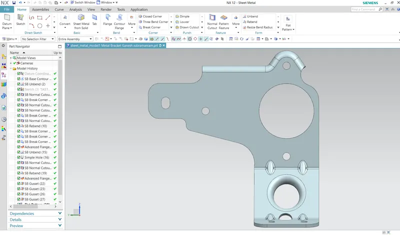
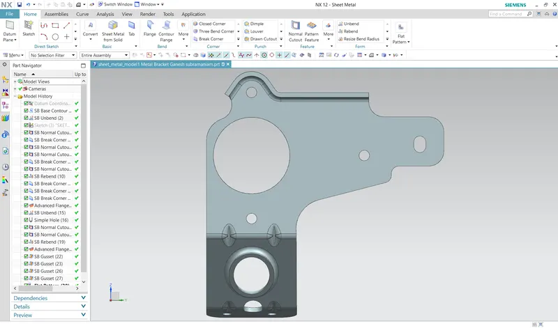
TOP VIEW:
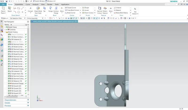
BOTTOM VIEW:
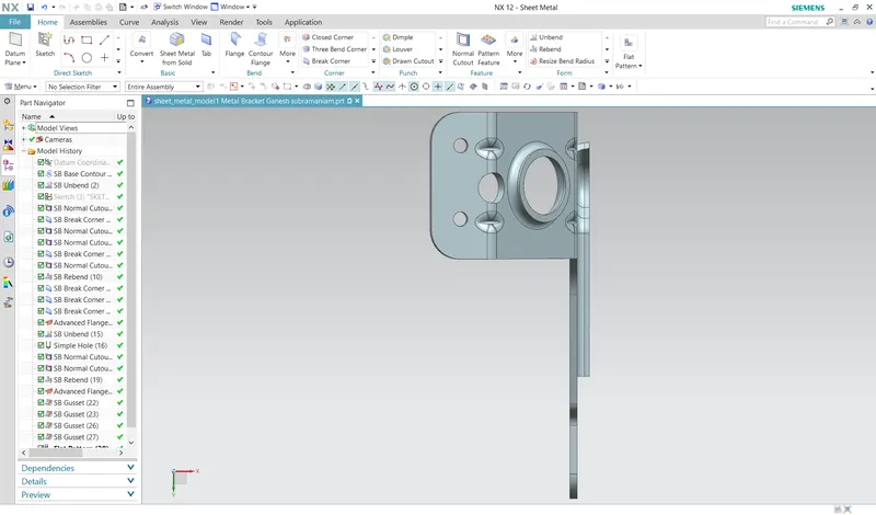
CONCLUSION:
In this project the Designing of Bracket sheet metal part 2 is been successfully designed in the sheet metal workbench of siemens NX.