Radar Mast & Final Assembly of Yacht
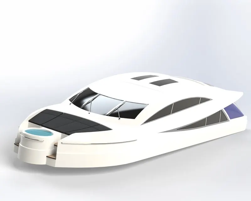
DESIGNING, MODELLING, ASSEMBLY and PHOTO RENDERING of SUNSEEKER PREDATOR YACHT
INTRODUCTION:
The Project Report is about the Designing, Modelling, Assembly and Photo Rendering of Sunseeker Predator YACHT using Solid Works and Solid Works Visualize.
OBJECTIVE:
The main objective of the project is to Design and Modelling each component required to make assembly of Sunseeker Predator YACHT in Solid Works and finally make a Photorealistic Rendering of the complete assembly of Sunseeker Predator YACHT.
ABSTRACT:
In this project, we will sketch and build a complete Sunseeker Predator YACHT using Solid Works.
We will learn how to create cut extrudes, revolve cuts, lofts, circular patterns for modelling - setting up of reference planes - curve generation - projected curve creation understanding how to insert the parts in assembly workspace - the creation of mates - the difference between float and fix parts - Width mate application.
We will also learn how to create photo-realistic renderings with real-time appearances and views.
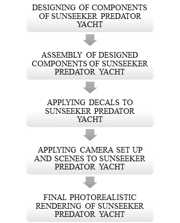
FLOW OF ACTION FOR DESIGNING CHOPPER METHODOLOGY:
- Designing of Components of Sunseeker Predator YACHT
- Assembly of Designed Components of Sunseeker Predator YACHT
- Applying Decals
- Camera Set-up and Scenes
- Final Photorealistic Rendering of Sunseeker Predator YACHT
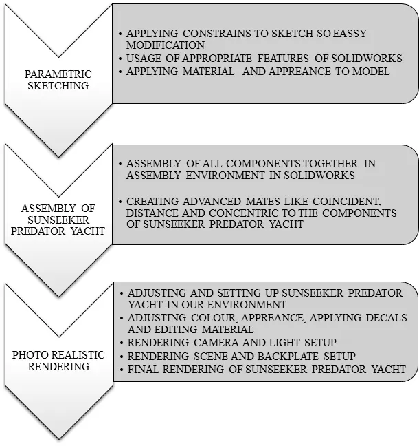
DESIGN METHODOLOGY AND FLOW DIAGRAM OF SUNSEEKER PREDATOR YACHT:
Parts of Sunseeker Predator YACHT:
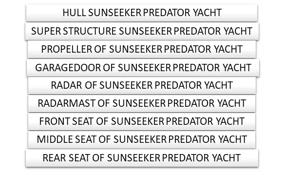
Sunseeker Predator YACHT consist of 9 parts they are as followed
- HULL SUNSEEKER PREDATOR YACHT
- SUPER STRUCTURE SUNSEEKER PREDATOR YACHT
- PROPELLER OF SUNSEEKER PREDATOR YACHT
- GARAGEDOOR OF SUNSEEKER PREDATOR YACHT
- RADAR OF SUNSEEKER PREDATOR YACHT
- RADARMAST OF SUNSEEKER PREDATOR YACHT
- FRONT SEAT OF SUNSEEKER PREDATOR YACHT
- MIDDLE SEAT OF SUNSEEKER PREDATOR YACHT
- REAR SEAT OF SUNSEEKER PREDATOR YACHT
FLOW DIAGRAM FOR YACHT DESIGNED PARTS:
COMMANDS USED:
- Line: This feature allows us to create a straight line. The line can be a solid line or a construction line.
- Circle: This feature allows us to create circles.
- Rectangle: This feature allows us to create squares or rectangles.
- Spline: This allows us to make curved lines
- Curve Projection: this is used for the projection of the curves made in different planes to create an intersected curve.
- Arc: This allows us to create arc.
- Projected Curve: It is a powerful tool which can project two different 2D splines from two different planes into a single spline or a curve in 3D which can meet our need. It is the most often used feature before creating any surface.
- Split: This feature is used to split to bodies using a sketch.
- Trim: This is used to trim sketches.
- Extend: This feature allows us to extend the sketches.
- Extrude Bose: This feature allows us to create solid bodies.
- Extrude cut: This feature allows us to create cuts or holes of any shape in the solid body.
- Swept Bose: This feature allows us to make a solid body along a curve path or create a curved solid body.
- Mirror: This feature allows us to create exact copy of the solid body using a reference plane or face.
- Revolve: This allows us to create revolve solid body around an axis.
- Linear Pattern: This allows us to create a pattern in a straight line.
- Circular Pattern: This allows us to create a pattern in a circle
- Fillet: This is used to create circular edges.
- Chamfer: This is used to create inclined edges.
- Plane: This feature is used to create new planes.
- Loft: This feature allows us to make solid bodies with uneven geometry.
- Dome: This feature is used to make a dome shaped solid over a flat solid body.
- Shell: This is used to make a hollow solid body.
- Mirror Entities: This is used to create a mirror of sketch.
- Split Entities: This is used to split a line into two or more parts.
- Split line: The Split line is used to divide parts into multiple bodies. You can use the Split line feature to save the new bodies when you split the part or use the Save Bodies to save them after the split is complete.
- Convert Entities - Converts selected model edges or Sketch entities into Sketch segments.
- Loft: this is creating a feature by making transitions between profiles. A loft can be a base, boss, cut, or surface. We can create a loft using two or more profiles. For a solid loft, the first and last profiles must be model faces or faces created by split lines, planar profiles, or surfaces.
- Fillet: this is creating a rounded internal or external face on the part. We can fillet all edges of a face, selected sets of faces, selected edges, or edge loops.
- Helix: this is creating a helix or spiral curve in a part. The curve can be used as a path or guide curve for a swept feature, or a guide curve for a lofted feature.
- Loft Surface: Loft Surfaces are surfaces generated by multiple 3D Curves or existing edges creating a smooth tangency between the selected curves.
- Surface trim: it is used to cut away material from a surface and provides two modes: Standard and Mutual.
- Extend Surface: it is used to extend the surface which is already created. There are different options available on the extended surface. We can extend the surface as same surface, or we can extend the surface tangent to the surface.
- Surface knit: it is used to knit the two free edges/open edges of the surfaces together. Also, it reduces the gap between the two edges of the surface.
- Sweep Surfaces: this is surfaces that are generated from a section curve positioned along a path.
- Filled Surface: this Surface feature constructs a surface patch with any number of sides, within a boundary defined by existing model edges, sketches, or curves, including composite curves.
- Ruled surface: it is used to obtain the extruded surface perpendicular to the plane and can be titled in certain angle
- Rollback: Rollback is yet another powerful tool that allows going back to any phase of design in case if we need to edit or add some features later. We can use roll-up bar while removing errors too. This reduces the rebuild time and avoids further errors in the children features.
Combine Tool:
- Combining Bodies – Add: In a multibody part, you can combine multiple bodies to create a single body.
- Combining Bodies – Subtract: In a multibody part, you can subtract one or more bodies from another body.
- Combining Bodies – Common: In a multibody part, you can create a body defined by the intersection of multiple bodies.
- Combine Property Manager: In the Combine Property Manager, you specify which bodies in a multibody part to add, subtract, or overlap.
Delete/Keep Body: You can select bodies to keep or delete using the Delete/Keep Body feature. This is useful in working with multibody parts with multiple configurations.
DESCRIPTION OF THE PARTS:
PARTS DESIGN:
In this project most of the parts are designed to be multiple body parts to make the workflow faster and simple. It makes a lot easier in the assembly phase and decreases rebuilding time. As it is a cosmetic model of the YACHT it is all solid modelling. The following are the individual parts designed in SOLIDWORKS, Assembled in SOLIDWORKS AND rendered in SOLIDWORKS Photo view 360.
HULL SUNSEEKER PREDATOR YACHT:
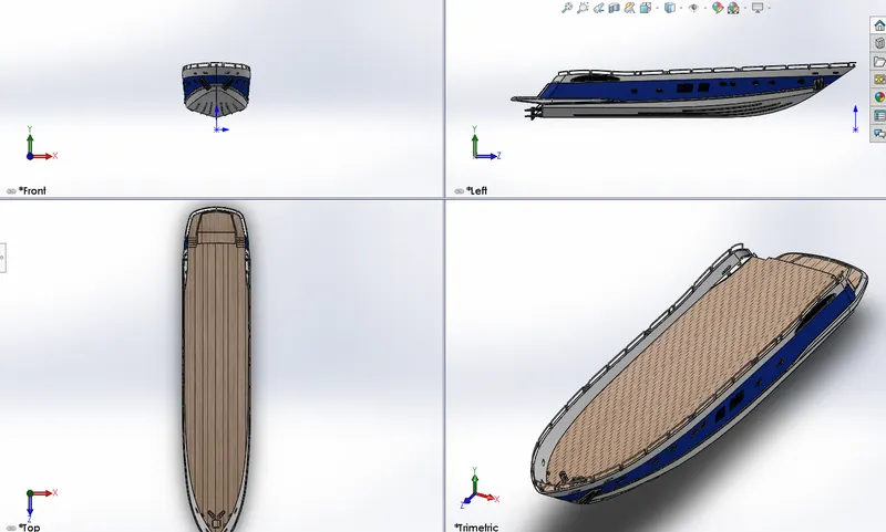
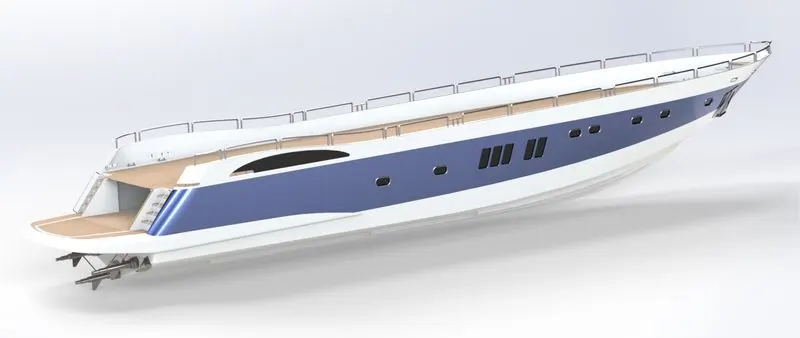
A hull is the watertight body of a ship There is a wide variety of hull types that are chosen for suitability for different usages, the hull shape being dependent upon the needs of the design. Shapes range from a nearly perfect box in the case of scow barges to a needle-sharp surface of revolution in the case of a racing multihull sailboat. The shape is chosen to strike a balance between cost, hydrostatic considerations, hydrodynamics and special considerations for the ship's role, such as the rounded bow of an icebreaker.
MODELING OF THE HULL SUNSEEKER PREDATOR YACHT:
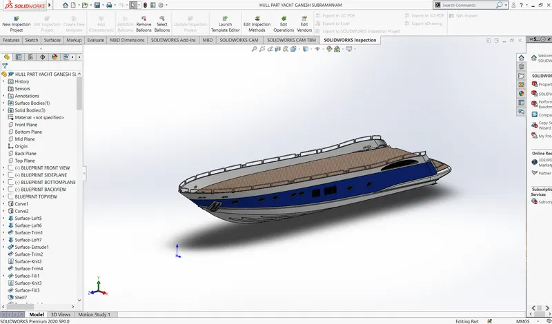
ISOMETRIC VIEW OF HULL SUNSEEKER PREDATOR YACHT:
RENDERING IMAGE OF THE HULL SUNSEEKER PREDATOR YACHT:
SUPER STRUCTURE SUNSEEKER PREDATOR YACHT
A superstructure is an upward extension of an existing structure above a baseline as stated above, superstructure consists of the parts of the ship or a boat, including sailboats, fishing boats, passenger ships, and submarines, that project above her main deck. This does not usually include its masts or any armament turrets.
MODELING OF THE SUPER STRUCTURE SUNSEEKER PREDATOR YACHT:
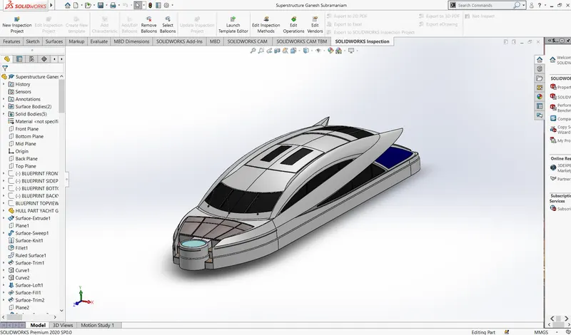
ISOMETRIC VIEW OF SUPER STRUCTURE SUNSEEKER PREDATOR YACHT:
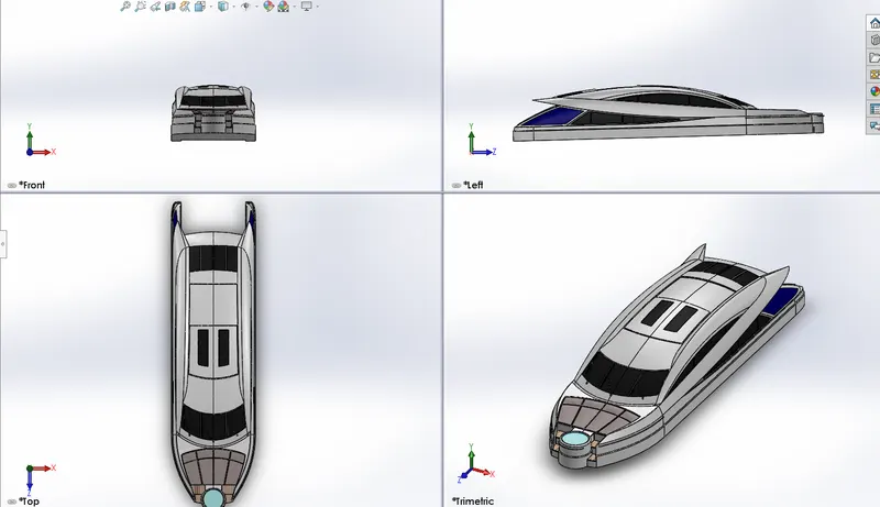
RENDERING IMAGE OF SUPER STRUCTURE YACHT:
PROPELLER OF SUNSEEKER PREDATOR YACHT:
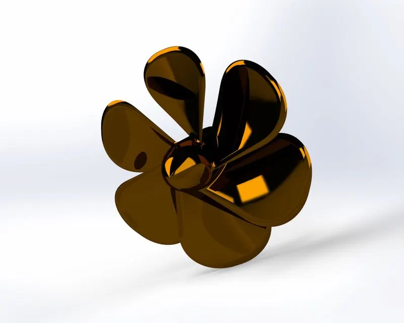
A propeller is a rotating fan-like structure which is used to propel the ship by using the power generated and transmitted by the main engine of the ship A ship can be fitted with one, two and rarely three propellers depending upon the speed and manoeuvring requirements of the vessel Boat propellers include blades that turn on a shaft, which is powered by the motor. Propellers can have 3, 4, or 5 blades. Typically, the more blades on the propeller, the more propulsion can be achieved. While the motor provides the power, the propeller is where all the action takes place
MODELING OF THE PROPELLER YACHT:
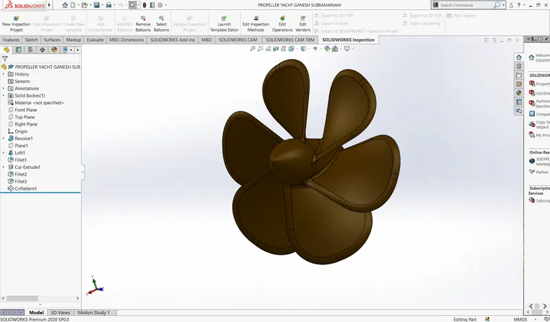
ISOMETRIC VIEW OF PROPELLER YACHT:
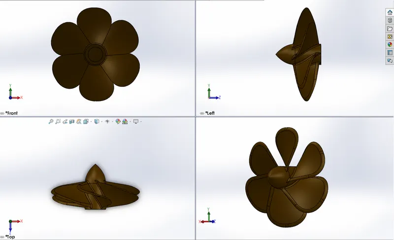
RENDERING IMAGE OF PROPELLER YACHT:
GARAGEDOOR OF SUNSEEKER PREDATOR YACHT:
A garage door is a large door on a garage that opens either manually or by an electric motor Garage doors are frequently large enough to accommodate automobiles and other vehicles. Small garage doors may be made in a single panel that tilts up and back across the garage ceiling. Larger doors are usually made in several jointed panels that roll up on tracks across the garage ceiling, or into a roll above the doorway. The operating mechanism is spring-loaded or counterbalanced to offset the weight of the door and reduce human or motor effort required to operate the door. Less commonly, some garage doors slide or swing horizontally. Doors are made of wood, metal, or fiberglass, and may be insulated to prevent heat loss.
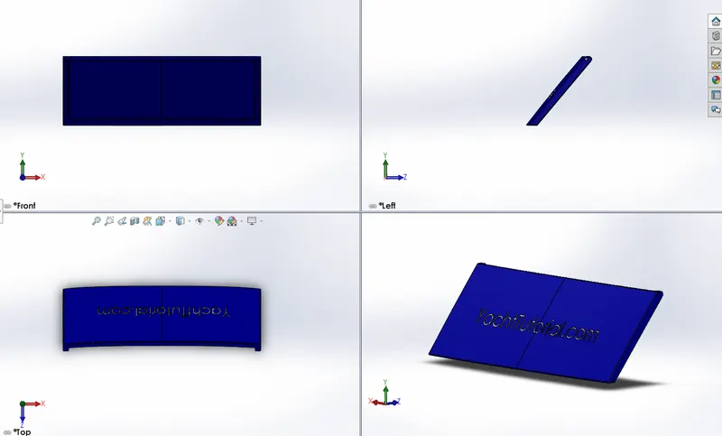
MODELING OF THE GARAGEDOOR YACHT:
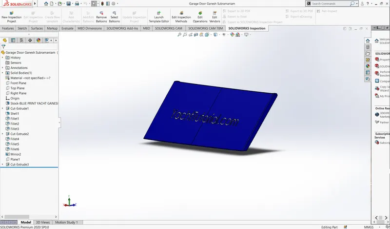
ISOMETRIC VIEW OF GARAGEDOOR YACHT:
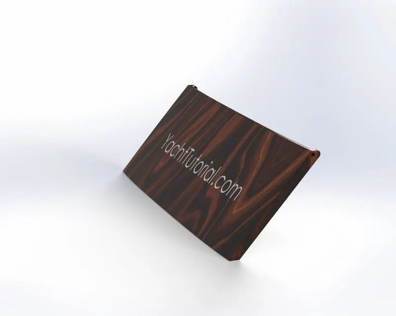
RENDERING IMAGE GARAGEDOOR OF YACHT:
RADAR OF SUNSEEKER PREDATOR YACHT:
The Radar is used to detect other ships and land obstacles, to provide bearing and distance for collision avoidance and navigation at sea. They are electronic navigation instruments that use a rotating antenna to sweep a narrow beam of microwavearound the water surface surrounding the ship to the horizon, detecting targets by microwaves reflected from them, generating a picture of the ship's surroundings on a display screen.
Radar is a vital navigation component for safety at sea and near the shore. Captains need to be able to manoeuvre their ships within feet in the worst of conditions and to be able to navigate "blind", when there is no visibility at night or due to bad weather. In addition to vessel-based marine radars, in port or in harbour, shore-based vessel traffic service radar systems are used byharbourmasters and coastguard to monitor and regulate ship movements in busy waters.
MODELING OF THE RADAR YACHT:
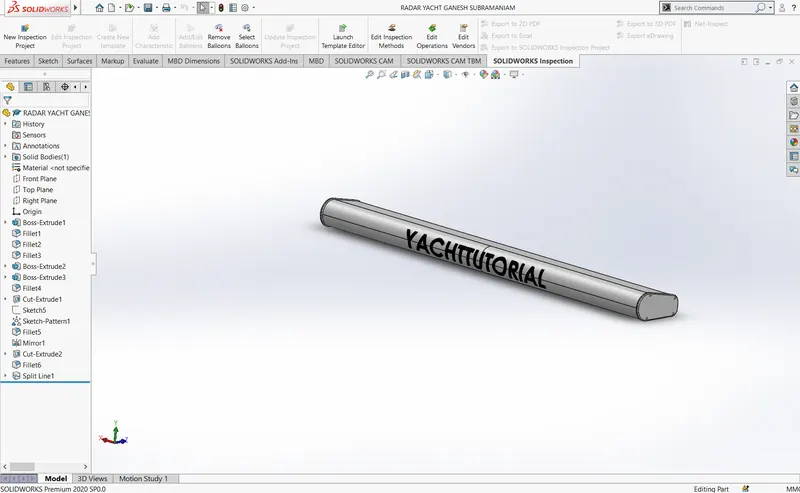
ISOMETRIC VIEW OF RADAR YACHT:
RENDERING IMAGE OF RADAR YACHT:
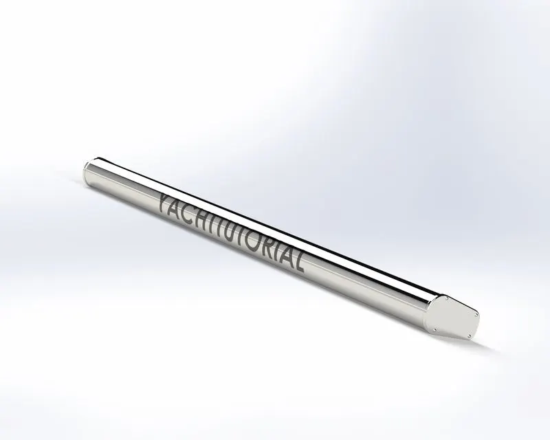
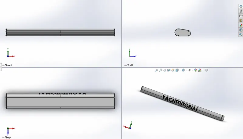
RADARMAST OF SUNSEEKER PREDATOR YACHT:
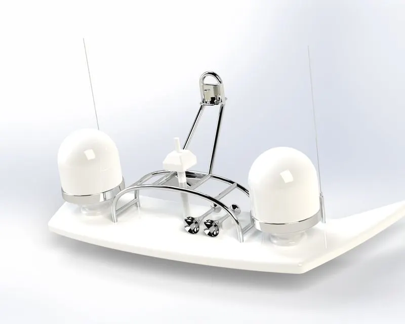
Radar mast is the pole that holds up the sails and radar on a ship. A tall spar or, now often, a hollow metal structure, sometimes in sections, rising vertically from the keel or deck of a vessel and used to support the sails, yards, radar and radio equipment
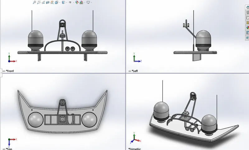
MODELING OF THE RADARMAST YACHT:
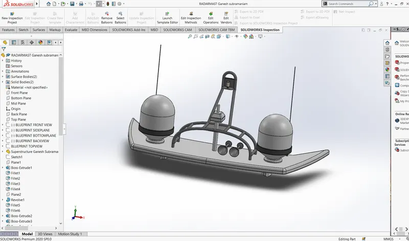
ISOMETRIC VIEW OF THE RADARMAST YACHT:
RENDERING IMAGE OF RADARMAST YACHT:
FRONT SEAT OF SUNSEEKER PREDATOR YACHT:
MODELING OF THE FRONT SEAT YACHT:
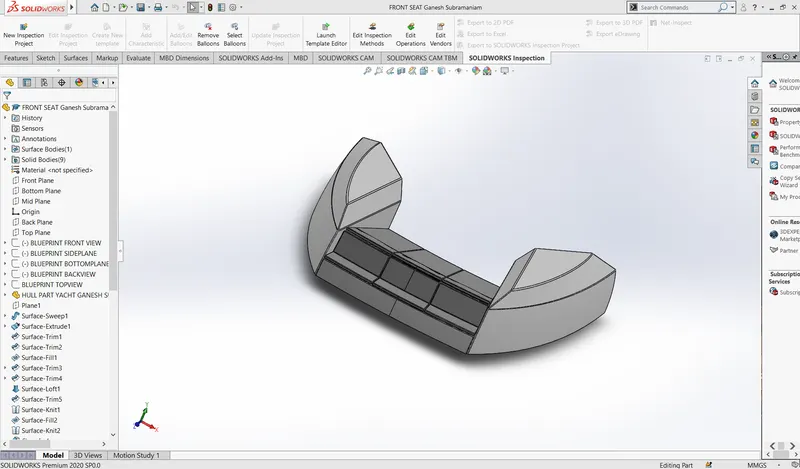
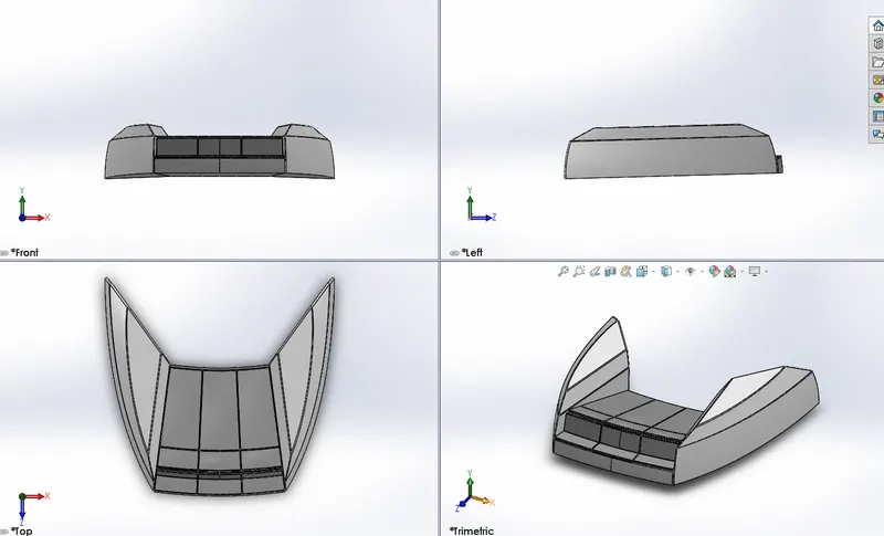
ISOMETRIC VIEW OF THE FRONT SEAT YACHT:
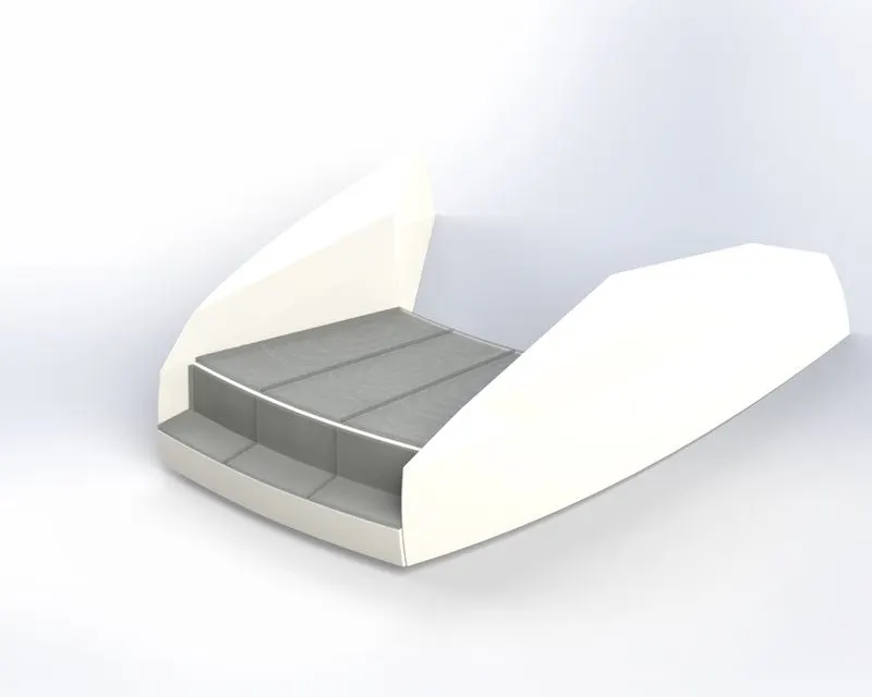
RENDERING IMAGE OF FRONT SEAT YACHT:
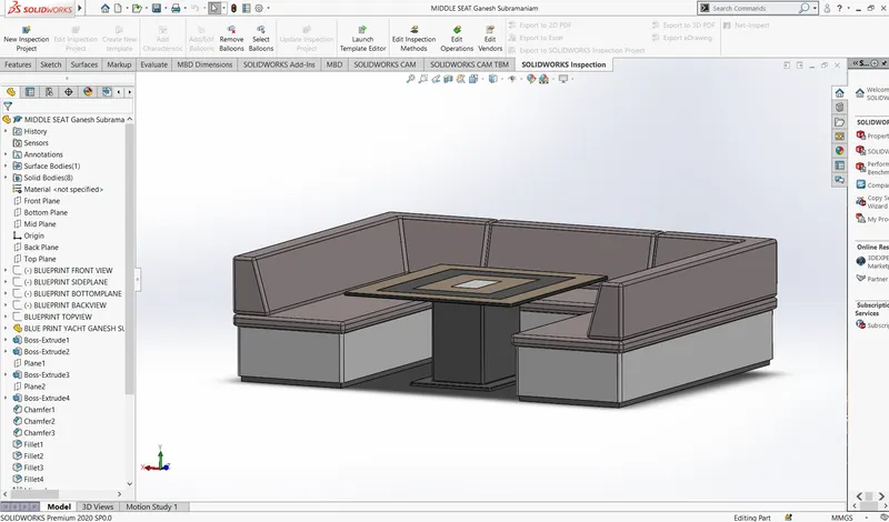
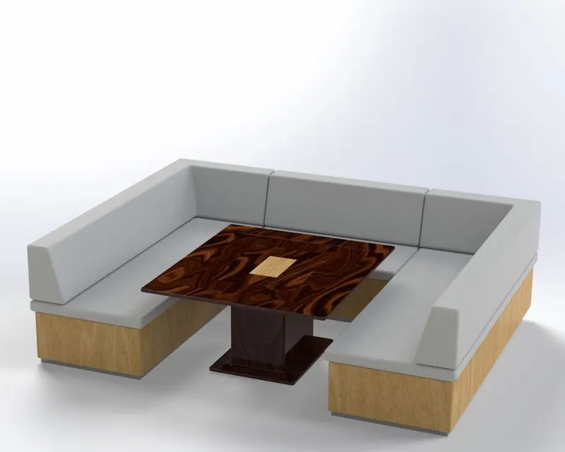
MIDDLE SEAT OF SUNSEEKER PREDATOR YACHT:
MODELING OF THE MIDDLE SEAT YACHT:
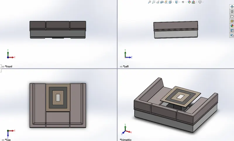
ISOMETRIC VIEW OF THE MIDDLE SEAT YACHT:
RENDERING IMAGE OF MIDDLE SEAT YACHT:
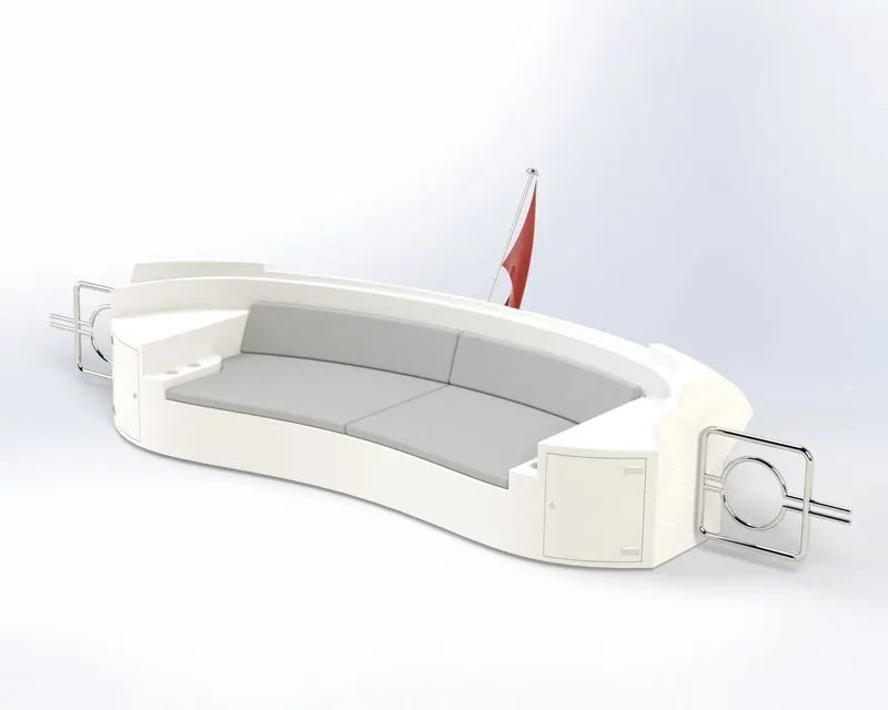
REAR SEAT OF SUNSEEKER PREDATOR YACHT:
MODELING OF THE REAR SEAT YACHT:
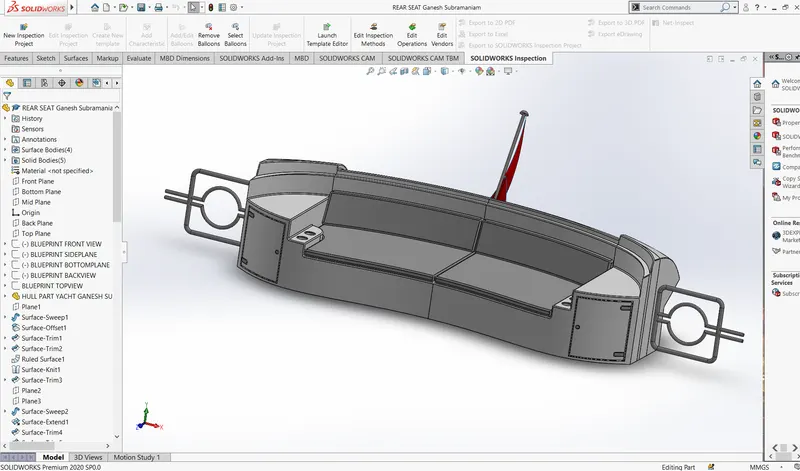
ISOMETRIC VIEW OF THE REAR SEAT YACHT:
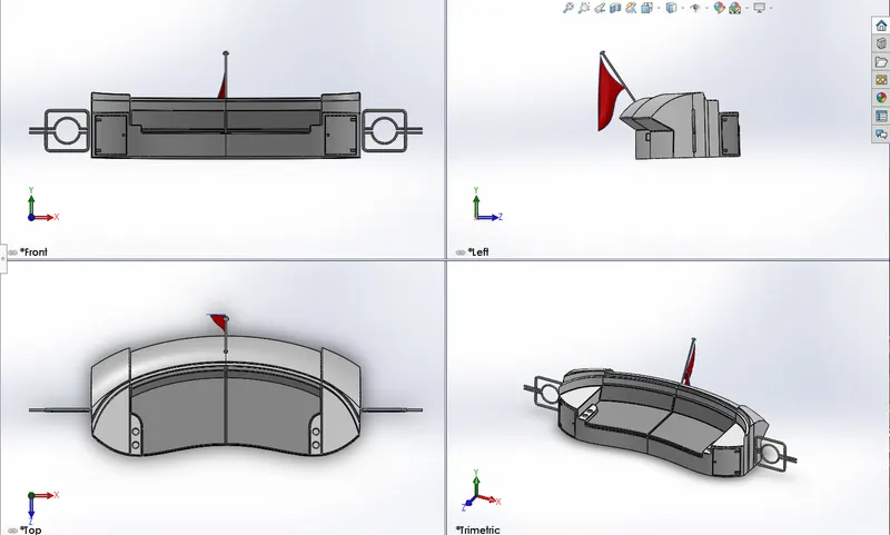
RENDERING IMAGE OF REAR SEAT YACHT:
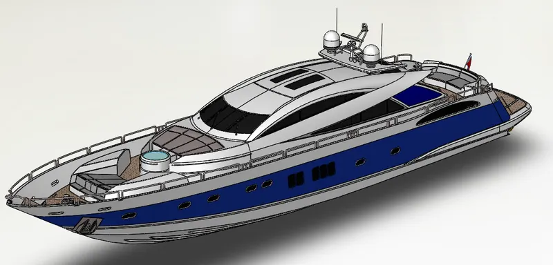
ASSEMBLY OF SUNSEEKER PREDATOR YACHT:
An Assemblies is a process in which parts, features and other sub-assembly are mated together. You can build complex assemblies consisting of many components, which can be parts or other assemblies called subassemblies into a single assembly part. Some of the mate used in the assembly are coincident, perpendicular, tangent and so on between the parts in the assembly.
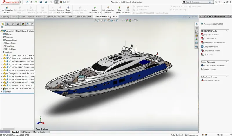
ISOMETRIC VIEW OF ASSEMBLY SUNSEEKER PREDATOR YACHT:
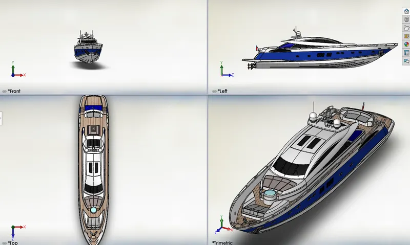
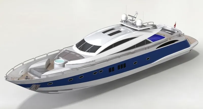
PHOTO REALISTIC RENDERING OF SUNSEEKER PREDATOR YACHT:
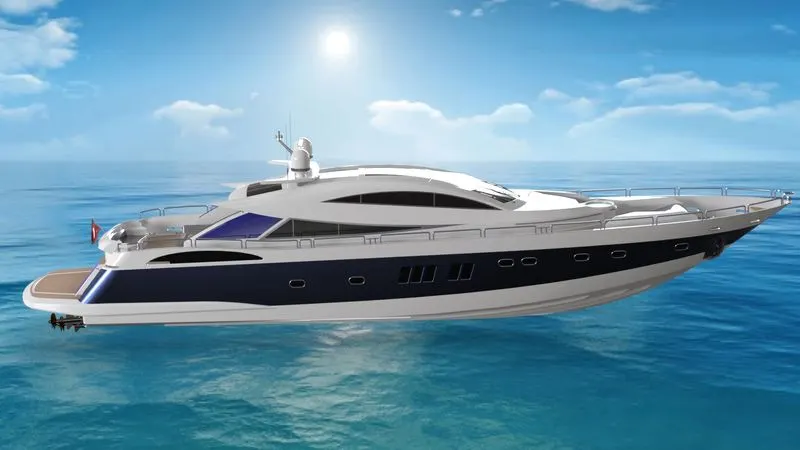
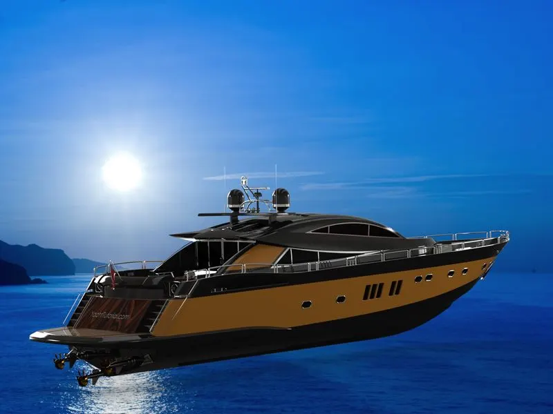
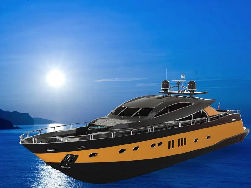
Rendering is the process of generating a photorealistic or non-photorealistic image from a 2D or 3D model by means of a computer program. The term "rendering" is also used to describe the process of calculating effects in a video editing program to produce the final video output. we can use Real View and Ambient Occlusion to add realism to your models without rendering. You can use Photo View 360 within SOLIDWORKS or Visualize, a standalone suite of tools, to produce photo-realistic renderings of your models.
BEFORE RENDERING OF SUNSEEKER PREDATOR YACHT:
AFTER RENDERING OF SUNSEEKER PREDATOR YACHT:
RENDERING SAMPLES:
MODEL 1:
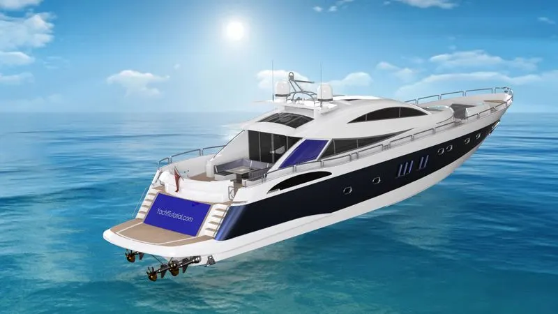
MODEL2:
CONCLUSION:
By this project I am able to Design and Model different parts in Solid Works. Assemble the created parts by applying respective mates in Assembly Solid Works. Finally using Photo Rendering for rendering Sunseeker Predator YACHT by Solid Works Visualize