Photo Realistic Rendering
DESIGNING, MODELLING, ASSEMBLY and PHOTO RENDERING of AMERICAN CHOPPER
INTRODUCTION:
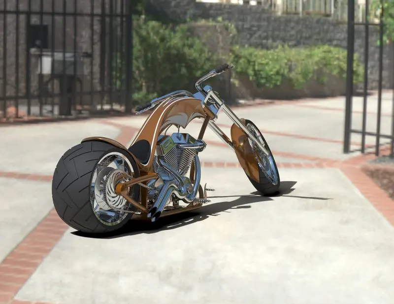
The Project Report is about the Designing, Modelling, Assembly and Photo Rendering of American Chopper using Solid Works and Solid Works Visualize.
OBJECTIVE:
To Design and Modeling each component required to make assembly of American Chopper in Solid Works and finally make a Photorealistic Rendering of the complete assembly of American Chopper.
ABSTRACT:
In this project, we will sketch and build a complete American Chopper using Solid Works.
We will learn how to create cut extrudes, revolve cuts, lofts, circular patterns for modelling - setting up of reference planes - curve generation - projected curve creation understanding how to insert the parts in assembly workspace - the creation of mates - the difference between float and fix parts - Width mate application.
We will also learn how to create photo-realistic renderings with real-time appearances and views.
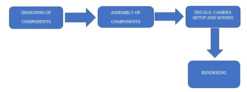
FLOW OF ACTION FOR DESIGNING CHOPPER:
- Designing of Components of chopper
- Assembly of Designed Components of chopper
- Applying Decals, Camera Set-up and Scenes
- Final Photorealistic Rendering
DESIGN METHODOLOGY AND APPROACH:
Parts of American Chopper:
American Chopper consist of 13 parts they are as followed
- Transmission belt
- Kickstand
- Front Fender
- Rear Fender
- Oil Tank
- Chain
- Pedal
- Front Wheel
- Rear Wheel
- Front Fork
- Chassis
- Engine
- Gas Tank
COMMANDS USED:
- Line: This feature allows us to create a straight line. The line can be a solid line or a construction line.
- Circle: This feature allows us to create circles.
- Rectangle: This feature allows us to create squares or rectangles.
- Spline: This allows us to make curved lines
- Curve Projection: this is used for the projection of the curves made in different planes to create an intersected curve.
- Arc: This allows us to create arc.
- Projected Curve: It is a powerful tool which can project two different 2D splines from two different planes into a single spline or a curve in 3D which can meet our need. It is the most often used feature before creating any surface.
- Split: This feature is used to split to bodies using a sketch.
- Trim: This is used to trim sketches.
- Extend: This feature allows us to extend the sketches.
- Extrude Bose: This feature allows us to create solid bodies.
- Extrude cut: This feature allows us to create cuts or holes of any shape in the solid body.
- Swept Bose:This feature allows us to make a solid body along a curve path or create a curved solid body.
- Mirror: This feature allows us to create exact copy of the solid body using a reference plane or face.
- Revolve: This allows us to create revolve solid body around an axis.
- Linear Pattern: This allows us to create a pattern in a straight line.
- Circular Pattern: This allows us to create a pattern in a circle
- Fillet: This is used to create circular edges.
- Chamfer: This is used to create inclined edges.
- Plane: This feature is used to create new planes.
- Loft: This feature allows us to make solid bodies with uneven geometry.
- Dome: This feature is used to make a dome shaped solid over a flat solid body.
- Shell: This is used to make a hollow solid body.
- Mirror Entities: This is used to create a mirror of sketch.
- Split Entities: This is used to split a line into two or more parts.
- Split line:The Split line is used to divide parts into multiple bodies. You can use the Split line feature to save the new bodies when you split the part or use the Save Bodies to save them after the split is complete.
- Convert Entities - Converts selected model edges or Sketch entities into Sketch segments.
- Loft: this is creating a feature by making transitions between profiles. A loft can be a base, boss, cut, or surface. We can create a loft using two or more profiles. For a solid loft, the first and last profiles must be model faces or faces created by split lines, planar profiles, or surfaces.
- Fillet:this is creating a rounded internal or external face on the part. We can fillet all edges of a face, selected sets of faces, selected edges, or edge loops.
- Helix: this is creating a helix or spiral curve in a part. The curve can be used as a path or guide curve for a swept feature, or a guide curve for a lofted feature.
- Loft Surface: Loft Surfaces are surfaces generated by multiple 3D Curves or existing edges creating a smooth tangency between the selected curves.
- Surface trim: it is used to cut away material from a surface and provides two modes: Standard and Mutual.
- Extend Surface: it is used to extend the surface which is already created. There are different options available on the extended surface. We can extend the surface as same surface, or we can extend the surface tangent to the surface.
- Surface knit: it is used to knit the two free edges/open edges of the surfaces together. Also, it reduces the gap between the two edges of the surface.
- Sweep Surfaces: this is surfaces that are generated from a section curve positioned along a path.
- Filled Surface: this Surface feature constructs a surface patch with any number of sides, within a boundary defined by existing model edges, sketches, or curves, including composite curves.
- Ruled surface:it is used to obtain the extruded surface perpendicular to the plane and can be titled in certain angle
- Rollback:Rollback is yet another powerful tool that allows going back to any phase of design in case if we need to edit or add some features later. We can use roll-up bar while removing errors too. This reduces the rebuild time and avoids further errors in the children features.
Combine Tool:
- Combining Bodies – Add: In a multibody part, you can combine multiple bodies to create a single body.
- Combining Bodies – Subtract: In a multibody part, you can subtract one or more bodies from another body.
- Combining Bodies – Common: In a multibody part, you can create a body defined by the intersection of multiple bodies.
- Combine Property Manager: In the Combine Property Manager, you specify which bodies in a multibody part to add, subtract, or overlap.
Delete/Keep Body: You can select bodies to keep or delete using the Delete/Keep Body feature. This is useful in working with multibody parts with multiple configurations.
1.PARTS DESIGN:
In this project most of the parts are designed to be multiple body parts to make the workflow faster and simple. It makes a lot easier in the assembly phase and decreases rebuilding time. As it is a cosmetic model of the bike it is all solid modelling. The following are the individual parts designed in SOLIDWORKS and rendered in SOLIDWORKS Photoview 360.
1.1.TRANSMISSION BELT:
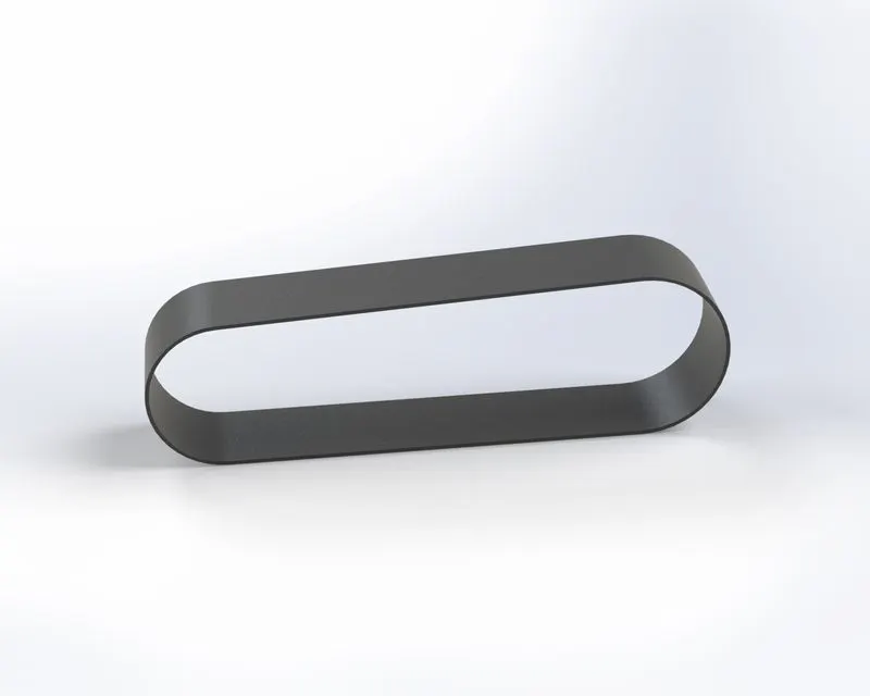
This transmission belt is a loop of flexible material designed to adapt to the two pulleys created on one side of the engine block and rotating pulleys mechanically.it is used to transmit power from engine to gearbox. It is a simple model created using very few features.
- Feature Tool: Extruded boss/base and fillet
- Sketch Tool: Sketch Geometry link line and offset entities
- Appearance: Matte Rubber
- Render Image: Photo view 360
PROCEDURE:
- Sketch on front plane by selecting it draw a horizontal line from origin and a 3-point arc. Apply realistic like tangent with line and give dimension to make it fully defined.
- Make an offset of 3.5 mm of the sketch inward direction
- Extrude the created sketch by given appropriate dimensions
- Apply fillets to all sides of Extrude sketch for smooth finish
- Give Appearance to the part
1.2. KICK STAND:
A Kick stand is a device on a motorcycle that allowed the bike to be kept upright without leaning against another object or the aid of a person. A Kick stand is usually a piece of metal that flips down from the frame and contact ground. A side style kickstand is used in this model. It is a single leg that simply flips out to one side usually left side. Side stand mounted right behind the bottom bracket can be bolted on either clamping the chain stays or to the bracket between them or welded into place as an integral part of the frame.
- Feature Tool: Pierce, Spline, Lofted Boss/Base, Extruded cut, Extruded Boss/Base.
- Sketch Tool: Ellipse, Spline
- Appearance: Chrome Steel
- Render Image: Photo View 360
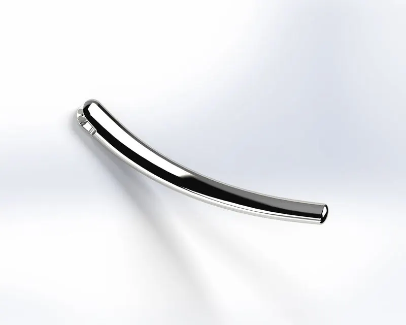
PROCEDURE:
- Insert Blueprint of chopper in the front plane adjust the location transparency and sketch on it. Draw two concentric circle with an offset of 4mm
- Draw a horizontal and vertical line front origin. Then a spline connects the circle center and tangent to the horizontal line and gets a projected sketch
- Sketch on top plane draw a horizontal line parallel to the line and draw on the front plane connected with the spline to make it fully defined
- Next sketch on right plane draw a spline from top to bottom with relation to origin and make it fully defined
- Remove the unwanted area using cut extrude, mirror the bodies and combine
- Apply fillet, chamfer and give appearance to it.
1.3. FRONT FENDER:
Front Fender is assembled over the front wheel which protects the wheel from foreign particles like, sand, mud, rocks, liquids, etc.
- Feature Tool: Revolve boss/base, spline and fillet.
- Sketch Tool: Sketch Geometry like line, spline and 3-point arc Extended entities and Trim Entities.
- Appearance: Painted Siena
- Render Image: Photo View 360
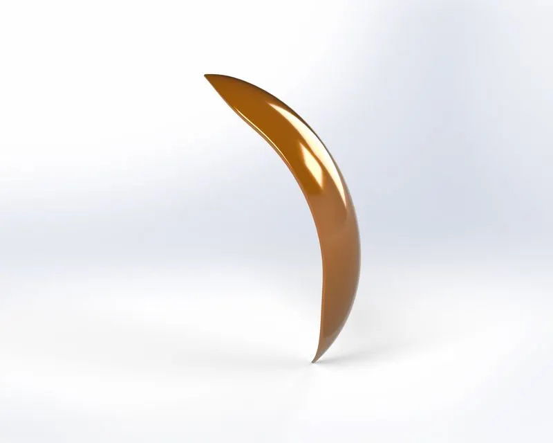
PROCEDURE:
- Sketch on Front Plane, by drawing a 3-point arc above the origin apply vertical relation with origin. Apply offset inwards to extrude make it closed sketch using extended entities and trim entities
- Revolve the sketch across the horizontal construction line at origin by given proper direction angle
- Remove the unwanted area using split tool and apply fillet.
- Give desired appearance to make it realistic.
1.4.OIL TANK:
American chopper has oil tank because the engine has a dry sump system meaning the oil is constantly pumped through the engine with an oil pump so the engine either has a tank or the oil pan is at lower engine height but behind the engine.
- Feature Tool: Extrude boss/base, combine, shell and fillet.
- Sketch Tool: Sketch Geometry like line, Spline and circle
- Appearance: Painted Siena
- Render Image: Photo View 360
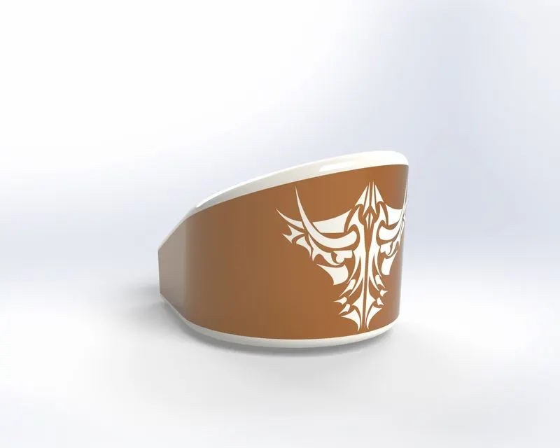
PROCEDURE:
- Sketch on top plane by drawing line 3-point arc and given relation dimension then for fully defining extrude it
- Sketch on the front plane by drawing a spline line dimension then to make it fully defined and extrude it by midplane through all and combine two separated bodies
- Apply fillet and given appearance.
1.5.CHAIN:
Chain acts as a connecting bridge between the engine and rear wheel which helps in transmitting power.
- Feature Tool: Extrude boss/base, Curve driven Pattern, mirror, Block and fillet.
- Sketch Tool: Sketch Geometry like line, straight slots, 3-point arc and circle
- Appearance: Chrome steel for plates and brushed metal for pin
- Render Image: Photo View 360
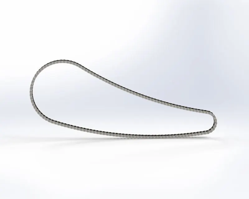
PROCEDURE:
- Sketch on front plane by drawing two circles of different diameter separated by distance by a distance and connect them using 3 point arc on both side then trim the unwanted area.
- Create a throwaway sketch which is used to create inside and outside chain link. Make a block of them and save it.
- Insert block on the large end of the drawn circle and make a coincident relation. Extrude the sketch by selecting hole in inside block to create pins.
- Use a curve driven pattern to get required number of pins and plates over the curve.
- Repeat the process over other curves to get desired output.
- Give desired appearance to make it realistic.
1.6.REAR FENDER:
The Rear Fender is thicker but shorter compared to the Front Fender. It does not have a pointed end like Front Fender rather rounded end. It is situated over the rear wheel which protect from foreign particles like, sand, mud, rocks, liquids, etc.
- Feature Tool: Revolve boss/base, spline, shell and fillet.
- Sketch Tool: Sketch Geometry like line, spline and 3-point arc Extended entities, Trim Entities and offset Entities.
- Appearance: Painted Siena
- Render Image: Photo View 360
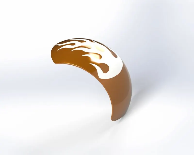
PROCEDURE:
- Sketch on Front Plane, by drawing a 3-point arc above the origin apply vertical relation with origin. Apply offset inwards to extrude make it closed sketch using extended entities and trim entities
- Revolve the sketch across the horizontal construction line at origin by given proper direction angle
- Remove the unwanted area using split tool and apply fillet.
- Give desired appearance to make it realistic.
1.7.PEDAL:
There are two Pedal left and right among them only the right pedal was sketched and designed in the part design environment and the left was made using the in-context feature of the assembly environment it is designed to sit into the hole provided at bottom of chassis on both sides. It is the gear shifting lever is located on the lower left side of motorcycle. By downing the pedal and lifting the pedal it shifts gear and right-side pedal is for foot resting.
- Feature Tool: Revolve boss/base, Extrude boss/base, dome, linear pattern, chamfer and fillet.
- Sketch Tool: Sketch Geometry like line, spline and circle
- Appearance: Chrome steel
- Render Image: Photo View 360
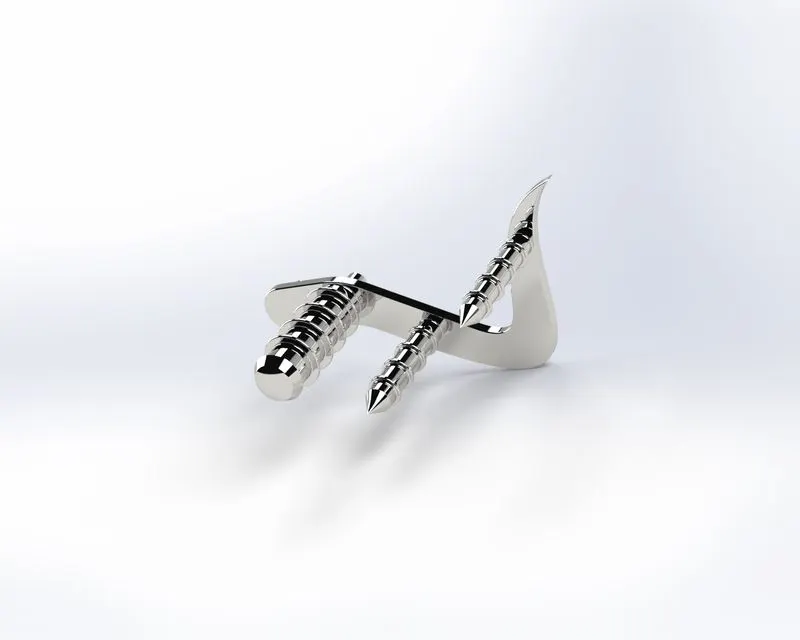
PROCEDURE:
- Draw a sketch on the front plane, line and spline from origin and given dimension to make it fully defined. Extrude it and apply fillet. Select the front surface of the extrude part and sketch on it by drawing two circles. Use a dome circle feature.
- Apply linear pattern across the boss extrude. use distance-distance chamfer to it
- Give appearance to the part.
1.8.FRONT WHEEL:
Front Wheel is a circular object connected at the front end of the chopper which helps for its movement. The front wheel is thinner than the rear wheel it is designed to be a multiple part consisting of the rotor, rim, tire and the caliper all in a single part.
- Feature Tool: Revolve boss/base, Extrude boss/base, Revolve cut, circular pattern, mirror, chamfer and fillet.
- Sketch Tool: Sketch Geometry like line, spline, circle, 3-point arc, rectangle, trim entities, extended entities, convert entities and offset entities.
- Appearance: Chrome steel for Rim, Brusher metal for Rotor, Painted Siena for Caliper and Matte Rubber Tire
- Render Image: Photo View 360
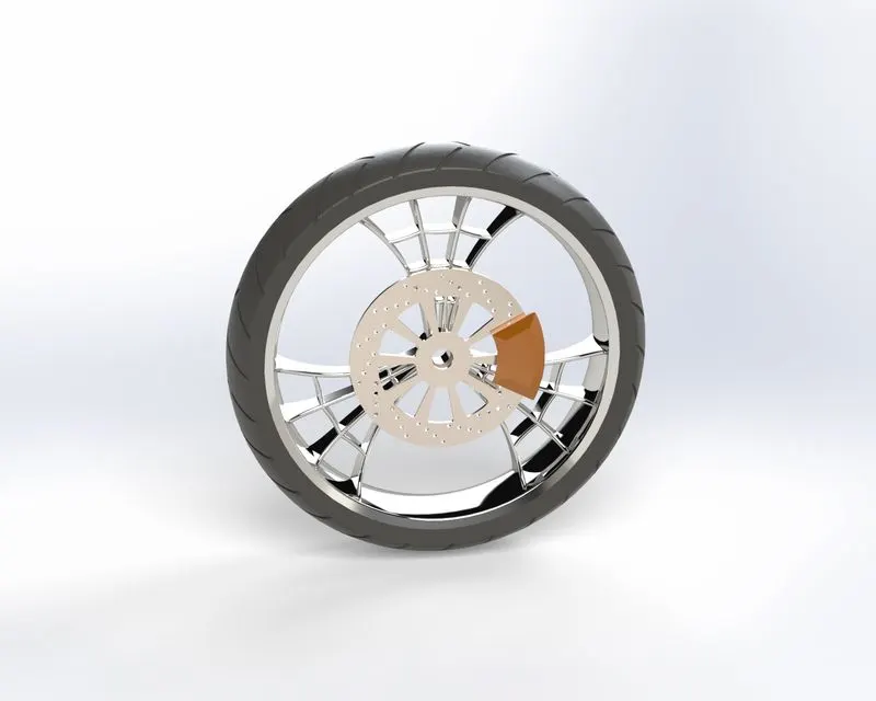
PROCEDURE:
- Select front plane and sketch the outer part of the wheel and dimension it to make fully defined
- Revolve the sketch across the temporary axis
- Sketch on the right plane by drawing a vertical construction line from the origin and one more line at an angle. Draw a spline and mirror at the three entities across vertical construction line extrude them
- For spider webbed design offset all the drawn three entities and remove the unwanted part using cut extrude.
- Connect the spokes using 3-point arc offset them and make it closed sketch by using lines. Extrude the sketch.
- Select the front plane and draw a spline from origin to remove unwanted area using extrude cut.
- Select spokes and use a circular pattern. Combine them to make a single solid body.
- ROTOR- Sketch on the front plane by drawing a circle and extruding it removed the unwanted portion. Use a circular pattern to create holes over the rotor.
- CALIPER- Draw circles and line as per design of body. Remove the unwanted area by trimming and extrude it, apply chamfer.
- TYRE- Use rim as convert entities and remove. draw rectangle and apply dimension, relation to make it fully defined. Extrude cut it and apply fillet.
- Give appearance to Rotor, Caliper and Tire.
1.9.FRONT FORK:
A Fork is a part of chopper that holds the front wheel. It consists of two blades which are joined at the top by a triple clamp. It acts as a shock absorber which allows just the front wheel to react during imperfection by isolating the other components from that motion.
- Feature Tool: Extrude boss/base, dome, Extrude cut, revolved cut, project curve, swept boss/base, combine, mirror and fillet.
- Sketch Tool: Sketch Geometry like line, spline, circle, convert entities and trim entities.
- Appearance: Chrome steel for fork, Matte rubber for handle and brake wire and Arial light
- Render Image: Photo View 360
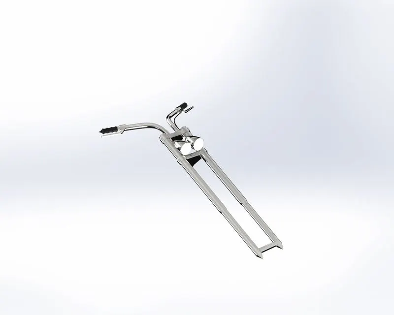
PROCEDURE:
- FORK TUBE: Sketch on the front plane by drawing a cylindrical diagram using line and give dimensions, relation to make it fully defined then revolve it.
- TRIPLE CLAMPS: Select top plane and draw a concentric circle to the fork tube and draw another circle left and upward. Connect the circle and make it fully defined by giving dimension then extrude it
- BULB: Select front plane draw a horizontal construction line, spline and revolve it. Move the bulb in z direction then fillet it.
- HANDLE AND BRAKE WIRES: Select top plane and draw the handle using spline make it fully defined. Draw a circle at the end of the spline and sweep along the path
- Select the bodies mirror it and combine.
- Give appearance to the fork to make it realistic.
1.10.REAR WHEEL:
Rear Wheel is a circular object connected at the rear end of the chopper which helps for its movement. The rear wheel is thicker than the front wheel it is designed to be a multiple part consisting of the rotor, sprocket, rim, tire and the caliper all in a single part.
- Feature Tool: Revolve boss/base, extrude boss/base, Revolve cut, circular pattern, mirror, chamfer and fillet.
- Sketch Tool: Sketch Geometry like line, spline, circle, 3-point arc, rectangle, trim entities, extended entities, convert entities and offset entities.
- Appearance:
- Chrome steel for Rim
- Brusher metal for Rotor
- Brusher metal for Sprocket
- Painted Siena for Caliper
- Matte Rubber for Tire
- Render Image: Photo View 360
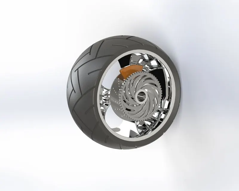
PROCEDURE:
- Select front plane and sketch the outer part of the wheel and dimension it to make fully defined
- Revolve the sketch across the temporary axis
- Sketch on the right plane by drawing a vertical construction line from the origin and one more line at an angle. Draw a spline and mirror at the three entities across vertical construction line extrude them
- For spider webbed design offset all the drawn three entities and remove the unwanted part using cut extrude.
- Connect the spokes using 3-point arc offset them and make it closed sketch by using lines. Extrude the sketch.
- Select the front plane and draw a spline from origin to remove unwanted area using extrude cut.
- Select spokes and use a circular pattern. Combine them to make a single solid body.
- ROTOR- Sketch on the front plane by drawing a circle and extruding it removed the unwanted portion. Use a circular pattern to create holes over the rotor.
- CALIPER- Draw circles and line as per design of body. Remove the unwanted area by trimming and extrude it, apply chamfer.
- SPROKET: Draw a circle and extrude it. Apply chamfer to the outer part and create teeth by cut extrude to it. Remove the unwanted portion by using cut extrude and apply fillet.
- TYRE- Use rim as convert entities and remove. draw rectangle and apply dimension, relation to make it fully defined. Extrude cut it and apply fillet.
- Give appearance to Rotor, Caliper, Sprocket and Tire.
1.11.GAS TANK:
A Gas Tank is also called a petrol tank it is safe to contain flammable fluids. Through any storage tank for fuel may be so called the term is typically applied to part of an engine system in which the fuel is stored and injected to the engine from the gas tank. The fuel tank is a reservoir that holds the fuel supply and helps to maintain its temperature at a level below its flash point.
- Feature Tool: Project curve, Swept Surface, combine, mirror, Boundary surface, knit surface, swept cut, shell and fillet.
- Sketch Tool: Sketch Geometry like line, spline, circle, convert entities and offset entities.
- Appearance: Painted Siena for gas tank and Fabric for driver seat
- Render Image: Photo View 360
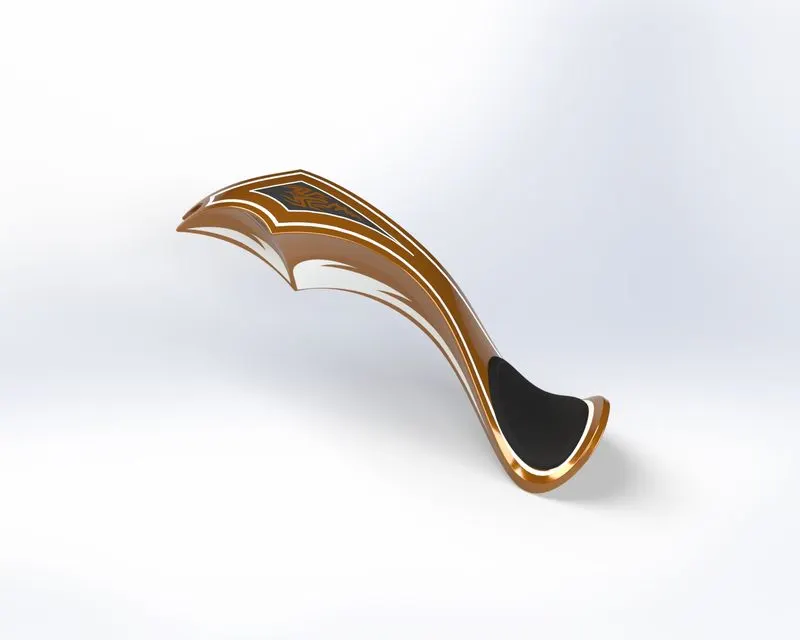
PROCEDURE:
- Insert the blueprint in the front plane and give proper dimensions for locating and renaming it. Sketch on the front plane by drawing construction line, spline as per the sketch picture and give dimension to make it fully defined
- Create a plane at the end point of the spline and sketch on it by drawing another spline and make a pierce relation with sketch 1, then sweep the surface
- Sketch on the top plane by drawing a spline and line. Trim the outside portion using a trim surface
- Create one more plane using the front plane and end point of surface 2 as reference. Sketch on it, by drawing a spline and a vertical construction line for dimension it.
- Draw the two sketches on the front plane and mid plane using spline and line then project curve and use lofted surface along projected curve.
- Repeat the procedure for sketching the remaining surface, mirror it and apply fillet.
- Remove the unwanted surface using a swept cut and apply shell to the body
- Give appearance to the tank as well as driver seat.
1.12.CHASSIS:
The most essential part of a vehicle on which all the components of a motorcycle like the suspension, wheel, gas tank, seats, handlebars etcetera are attached to this base structure which lends a motorcycle its strength and ability to handle well. The chassis is structurally supports the object in its construction and function it bears all the stresses on the chopper in both static and dynamic condition.
- Feature Tool: Extrude boss/base, dome, extrude cut, revolved cut, project curve, swept boss/base, Revolve boss/base, combine, mirror, Chamfer and fillet.
- Sketch Tool: Sketch Geometry like line,3 point arc, spline, circle, convert entities and offset entities.
- Appearance: painted Siena
- Render Image: Photo View 360
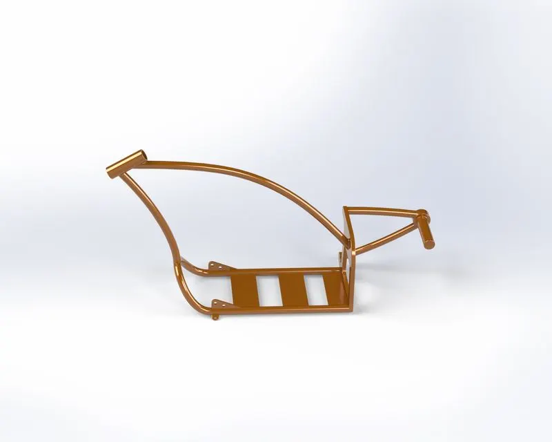
PROCEDURE:
- Insert blueprint of chopper in the front plane adjust the location, transparence and sketch on it draw two concentric circle with an offset of 4mm
- Draw a horizontal and vertical line from origin. Then a spline connects the circle center and tangent to the horizontal line and gets a projected sketch
- Sketch on the top plane, draw a horizontal line parallel to the line and draw on the front plane connected with the spline to make it fully defined
- Next sketch on right plane draw a spline from top to bottom with relation to original and make it fully defined.
- Remove the unwanted area using cut extrude mirror the body and combine.
- Apply fillet, chamfer and appearance to it.
1.13.ENGINE:
The engine is the heart of the vehicle. It converts chemical energy to the heat energy, which is then used to do the work, the rotary motion in the engine is transferred to the rear wheel through chain and sprocket.
- Feature Tool: Extrude boss/base, dome, extrude cut, revolved cut, project curve, composite curves, swept boss/base, Revolve boss/base, combine, mirror, Chamfer and fillet.
- Sketch Tool: Sketch Geometry like line,3 point arc, spline, circle, convert entities and offset entities.
- Appearance: chrome steel
- Render Image: Photo View 360
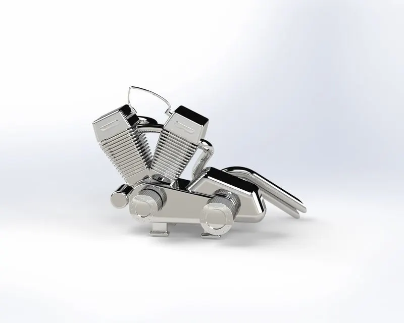
PROCEDURE:
- Insert the picture according to x, y, z reference, select the front plane draw a diagram of the base of engine by using line and 3-point arc, extrude it. Then extrude the large circle and small one.
- Sketch on the front plane by line entities then extrude it and give fillet to the base of the engine.
- Select a top plane draw the pully by line and then turn on a temporary axis to revolve it.
- Sketch on pully on the edge then draw rectangle and extrude towards the outside to next surface then select the sketch and make circular pattern.
- Select the outer face of the pulley and sketch on it draw a circle inward then draw a small circle vertical to origin use the circular pattern feature select the center point respectively and coincide. Then use the cut extrude feature to remove the material.
- Select the front plane to create the cylindrical part of the engine. Draw a line from origin again draw a line which will be colinear to line. Generate the new plane by selecting the line and end point of the line. Sketch in a new plane, draw a rectangle and extrude it upwards use fillet as well. Create an angle rectangle to the new plane and use cut extrude.
- Draw a curve sketch 2D diagram in two different plane by ensuring the end point should be same use the feature like convert entities construction line spline after getting projected curve draw two concentric circles make use of pierce relation to curve then sweep it.
2.ASSEMBLY OF DESIGN COMPONENTS:
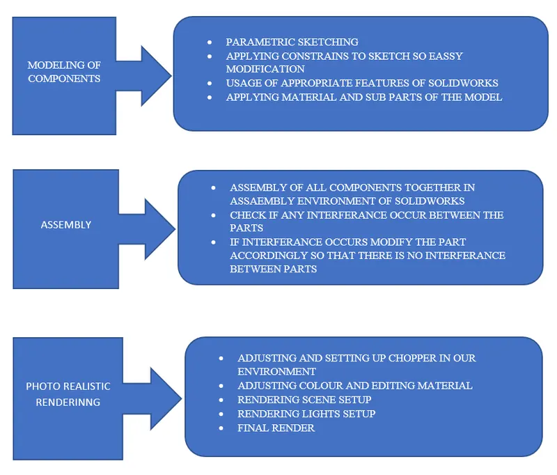
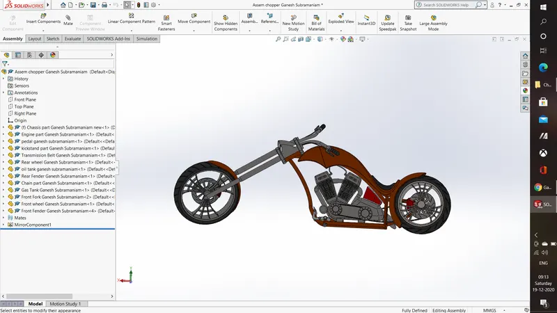
Combining multiple parts that fit together to create assemblies is called ASSEMBLY in SOLIDWORKS we integrated the parts in an assembly using mate such as concentric and coincident. Mates define the allowable direction of movement of the components.
STEPS FOLLOWED IN ASSEMBLY OF CHOPPER
- STEP-1: All the parts/components which are designed in the parts file are to be inserted in assembly file one by one as per requirement
- STEP-2: Apply mates to each individual part with other parts for proper alignment.
- STEP-3: Apply mate’s conditions to wheel and kick stand with top plane to snap it to the floor
3.APPLYING DECALS, CAMERA SET UP AND SCENCES:
- APPLYING DECALS: In this section decals are applied to gas tank, oil tank and rear wheel.
- CAMERA SET-UP: Camera set-up is essential for the final rendering of the chopper which helps in showcasing image
- SCENES AND LIGHT: Check for appropriate scenes and proper light set-up to make the chopper realistic in final rendering.
- FINAL RENDERING: In this we are going to render our chopper to make it realistic.
4.RENDERING IMAGE:
Rendering of the solid works model is done using Photo view 360 and Solid works Visualize.
STEPS FOLLOWED:
- Import: Import the assembly file into the solid works photo visualize
- Appearance: Give/change appearance to parts to make it more realistic
- Scenes: add scenes as the background and choose proper location
- Output: Make a fast rendering and check the output. Ones satisfied with everything go for final rendering
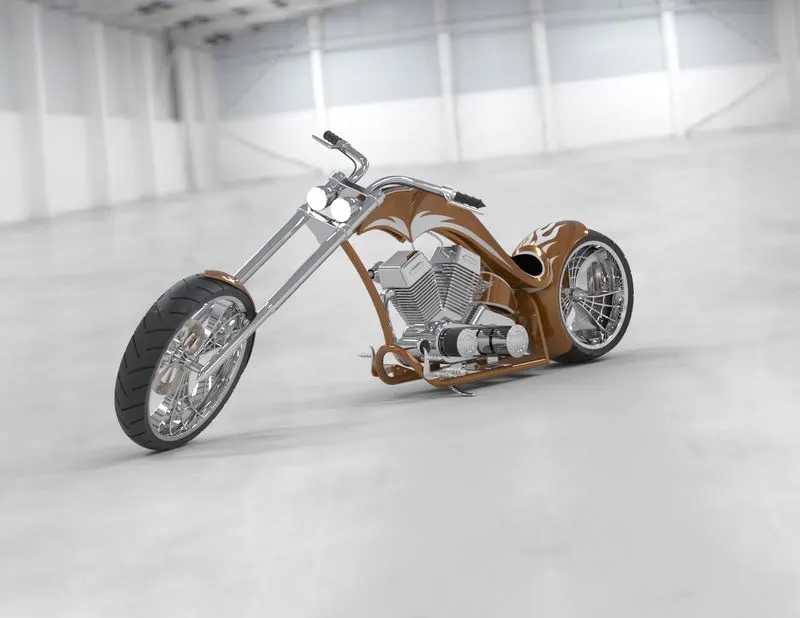
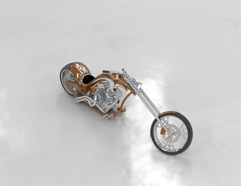
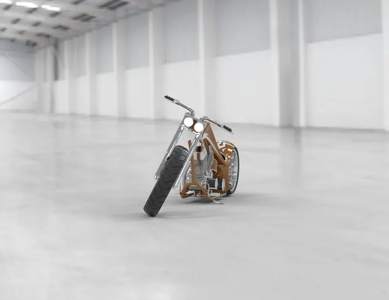
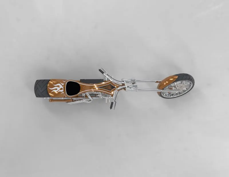
FINAL RENDERING IMAGE:
ISOMETRIC VIEW:
SIDE VIEW:
TOP VIEW:
CONCLUSION:
At the end of the project each component design individually in part file and assembly them to complete. Chopper design. Additional Apparency/setup like decals, scenes, camera, light, etc given to make it more realistic and finally rendered after placing designed chopper in decent background scenes.