Advanced Sheet Metal Design Using NX Cad Challenge_6_Bracket
Creation of Bracket using nxcad features
Objective - Create bracket metal part from a 2d drawing using NXcad features.
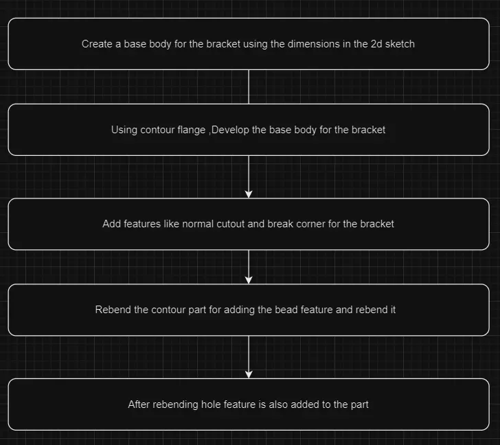
The creation of a bracket in Siemens NX CAD begins with the development of the base body using a 2D sketch as a reference.Once the base body is established, the Contour Flange feature is applied. This allows for the extrusion and shaping of the bracket's profile, creating the primary structure that will be further refined and detailed.
Following the formation of the base, additional features such as the Normal Cutout and Break Corner are introduced. The Normal Cutout feature is used to remove material in specific areas, tailoring the bracket to its functional requirements. The Break Corner feature is then applied to soften sharp edges, improving both the appearance and structural integrity by reducing stress concentrations.
To further enhance the bracket’s rigidity, a Bead feature is added after the part has rebent. Rebending repositions the flange, making it possible to apply the bead along the desired path. This step is crucial for adding strength while keeping the bracket lightweight. After rebending, the Local Radius tool is used to check the radii of the inner and outer parts of the bead, ensuring that the curvature meets design specifications.
The final step in the process is adding a Hole feature, which is positioned according to the bracket’s design requirements. This hole serves functional purposes, such as allowing for fastening or assembly. Each step in this process, from base creation to final feature addition, is carefully executed to ensure that the bracket meets all design and functional criteria.
Conclusion -
The process of creating the bracket in NX CAD demonstrates the importance of precision and methodical execution in design and manufacturing. From the initial base body creation to the addition of advanced features like the contour flange, bead, and cutouts, each step is crucial in shaping a part that meets both aesthetic and functional requirements. The careful application of rebending and radius inspection ensures structural integrity, while the final hole feature provides the necessary functionality for assembly.
Images are added in a zip file.
(Not uploading due to bigger size)