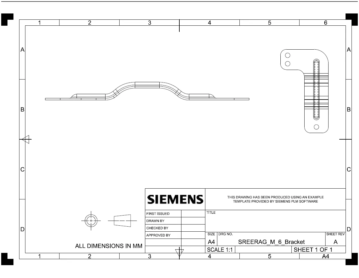
Advanced Sheet Metal Design Using NX Cad Challenge_6_Bracket
Title of the Project: Comprehensive Sheet Metal Component Modeling using Siemens NX CAD
Objective:
The primary objective of this project is to meticulously model a sheet metal component utilizing the tools and features offered by Siemens NX CAD. This report aims to provide a detailed explanation of the design process, methodologies employed, and the specific tools utilized to create a robust and manufacturable sheet metal part.
Introduction:
Siemens NX CAD is an advanced software solution that facilitates precise CAD/CAM modeling. This project focuses on leveraging its capabilities for sheet metal component design, ensuring efficiency and accuracy in the modeling process.
Design Methodology / Approach:
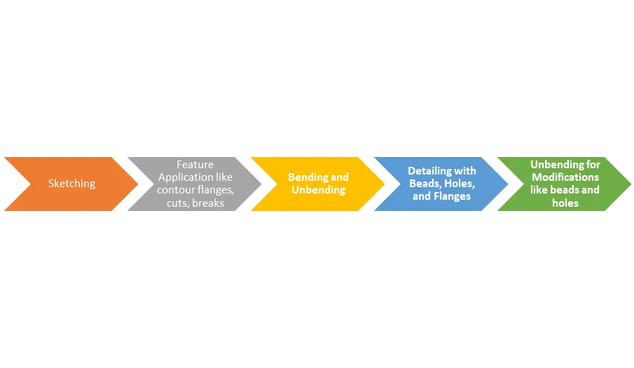
Open New Sheet Metal Part in NX CAD:
Initiate the design process by creating a new sheet metal part in Siemens NX CAD.
Sketching:
Employ sketching tools to outline the desired shape and structure of the sheet metal component.
Feature Application:
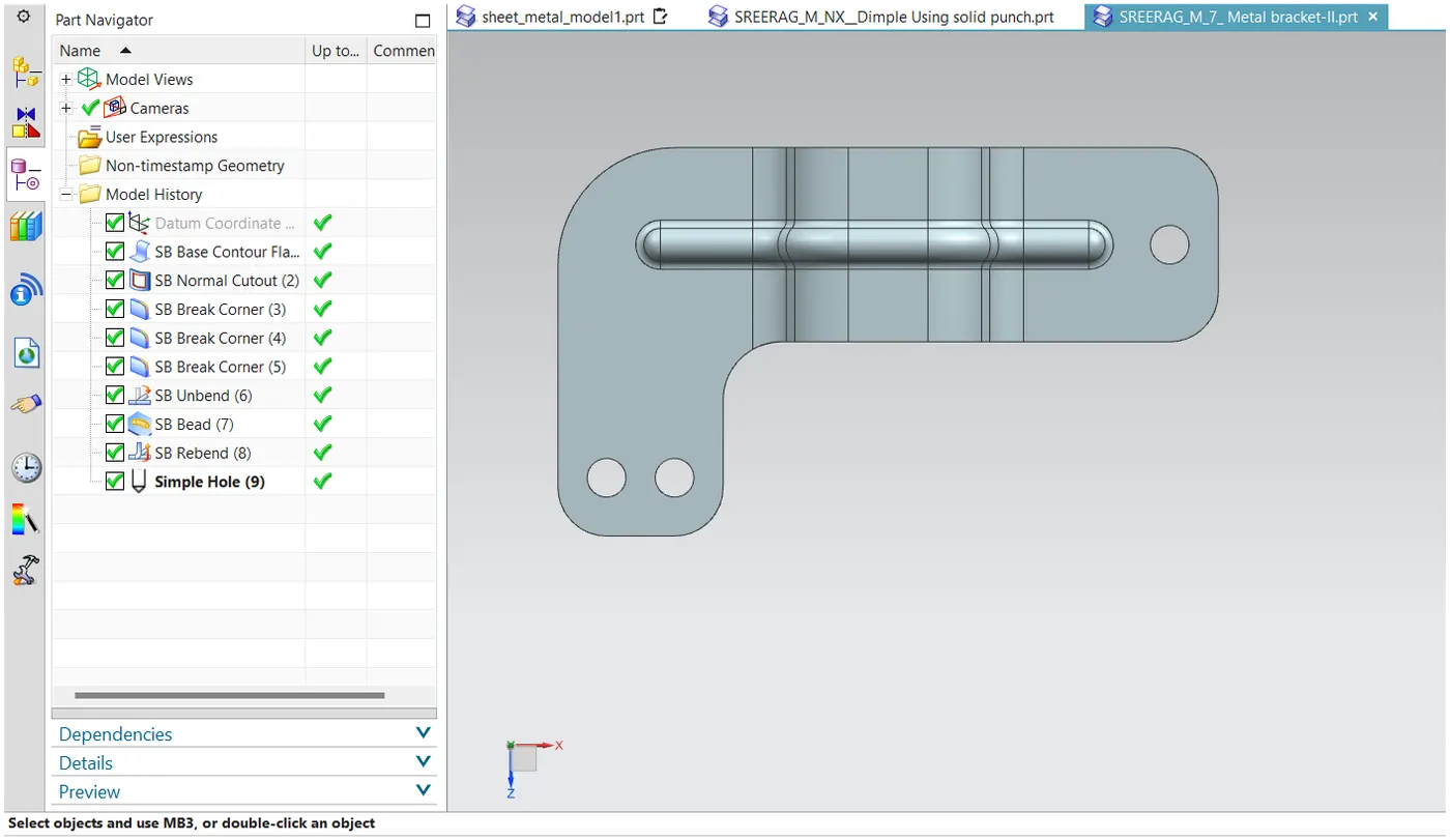
Apply conour flanges, cuts, breaks, and other relevant features using the designated tools.
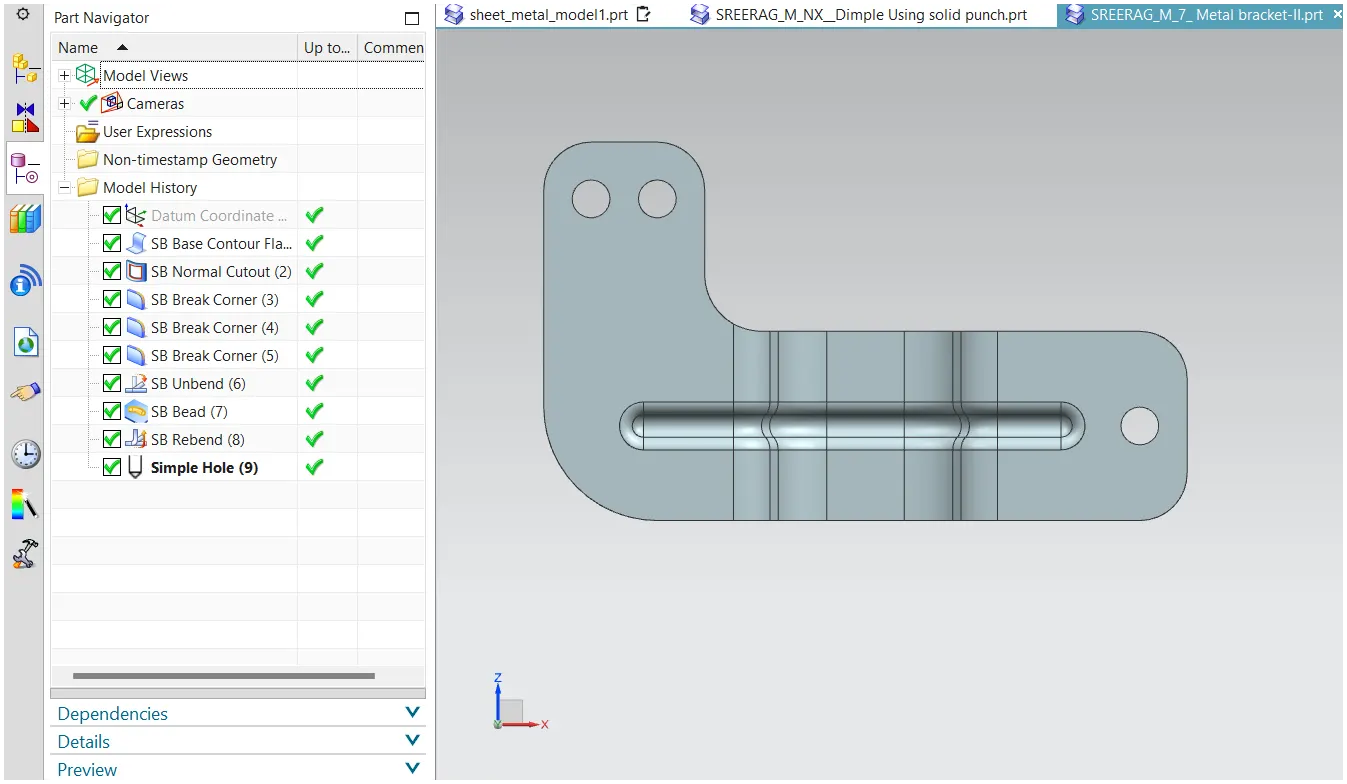
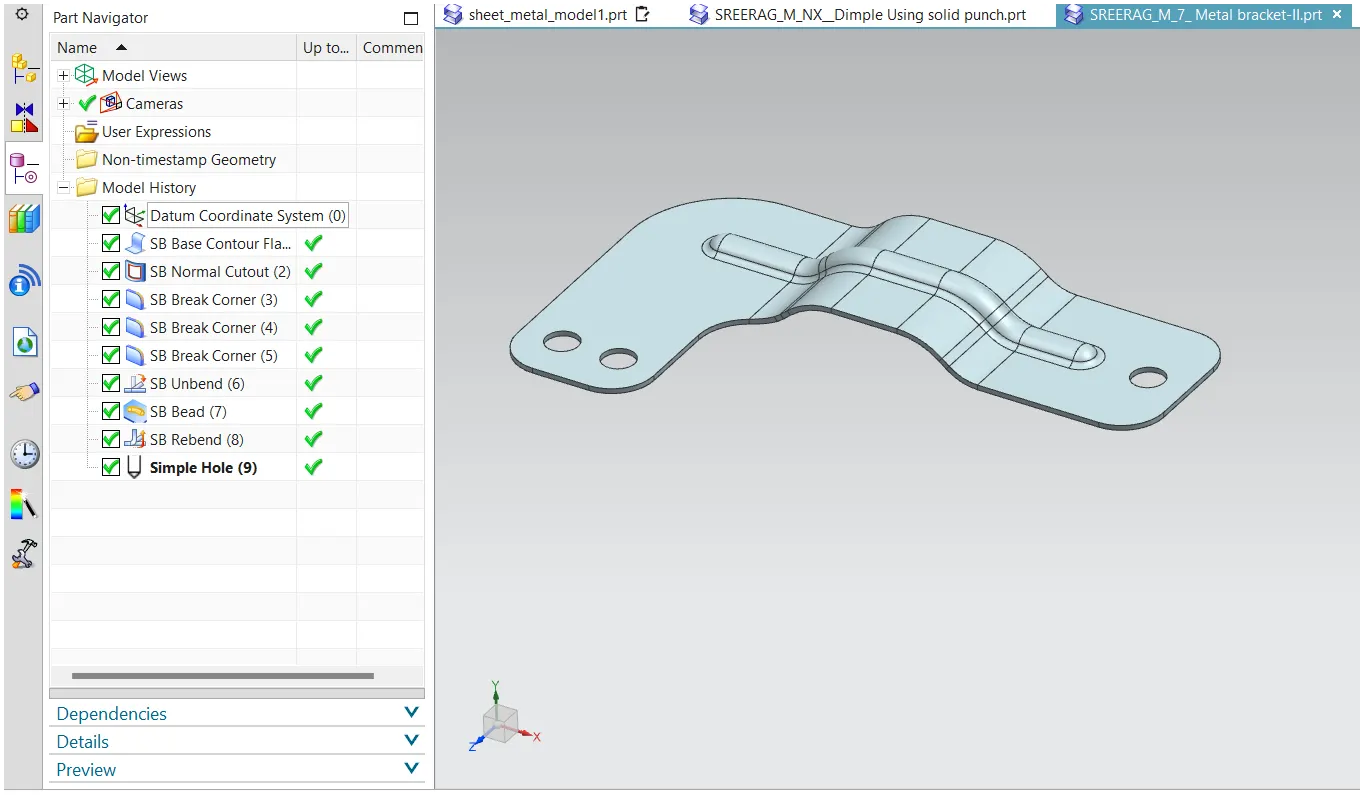
Utilize bending and unbending tools to shape and visualize the sheet metal component in both its formed and flat states.
Detailing with Beads, Holes, and Flanges:
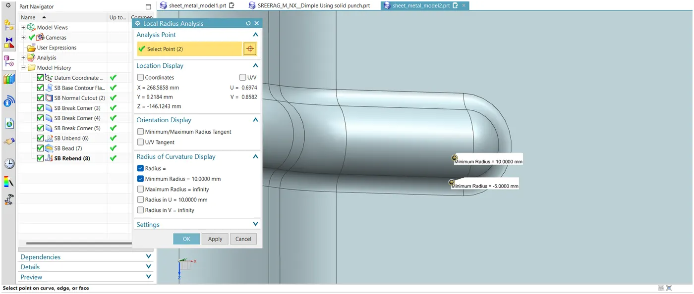
Add structural details using features like beads for stiffness, holes for perforations, and flanges for additional support.
Unbending for Modifications:
Unbend the model as needed to make modifications and adjustments.
Flat Pattern Creation:
Generate a flat pattern, incorporating all design details, for comprehensive documentation.
Optional: Drafting for Customer Understanding:
Create a detailed drawing sheet using the drafting tool if required, providing clarity to the customer.
Description (Tools/Features Used):
• Sketching Tools: Employed for initial profile creation.
• Contour Flanges: Used to generate sheet metal from 2D sketches.
• Cuts and Breaks: Applied for shaping and detailing.
• Bending/Unbending Tools: Facilitated the visualization of the sheet metal in both formed and flat states.
• Beads, Holes, and Flanges: Added structural details for strength and functionality.
• Flat Pattern Command: Created a 2D representation of the unbent sheet metal for documentation.
• Drafting Tool (Optional): Used for creating detailed drawings for customer understanding.
Bending and Unbending: