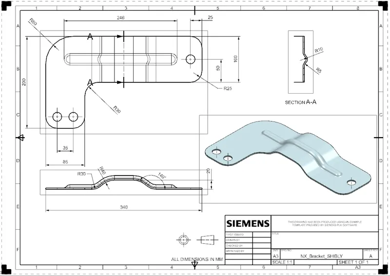
Advanced Sheet Metal Design Using NX Cad Challenge_6_Bracket
BRACKET DESIGN
Objective:
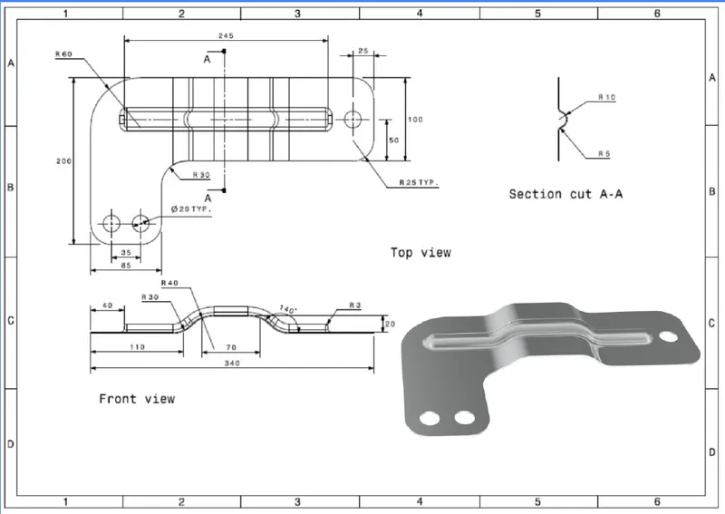
Design a bracket from the given draving;
Introduction:
We will design the bracket as per the drawing using NX-CAD on sheet metal workbench.
And we will its drawing.
Design Methodology:
1. Draw a sketch as per the sheet metal section as shown in drawing.
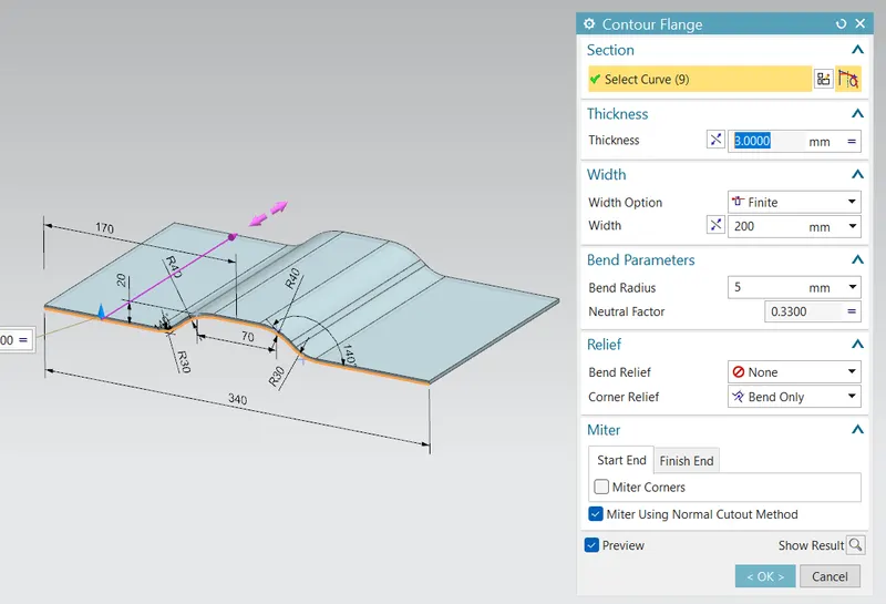
2. create a sheet metal of thickness 3mm using contour flange command.
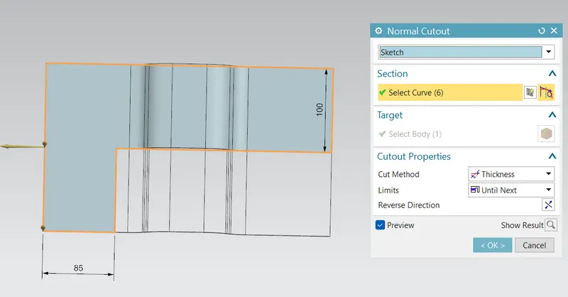
3. Create a new L-shaped sketch on the plane parallel to the flange surface.
4. Using command 'Normal cutout' removed the unwanted elements from the sheet.
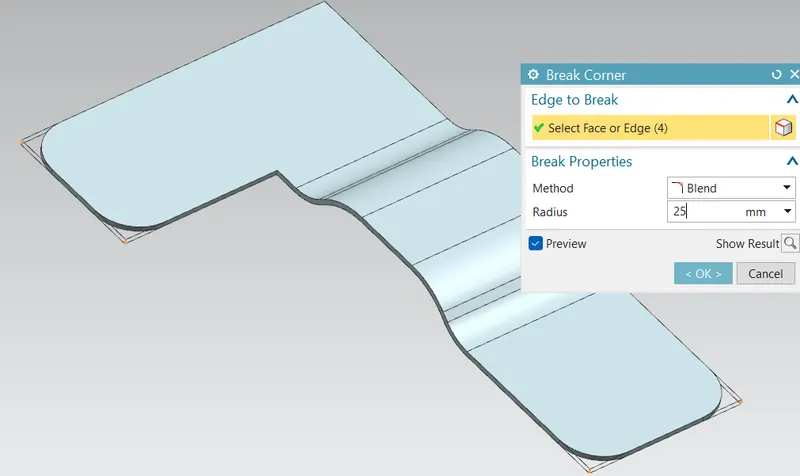
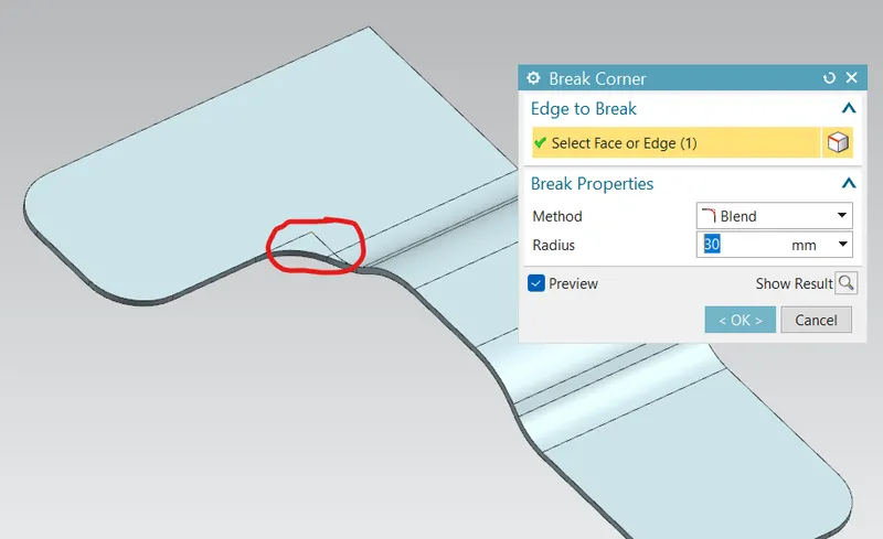
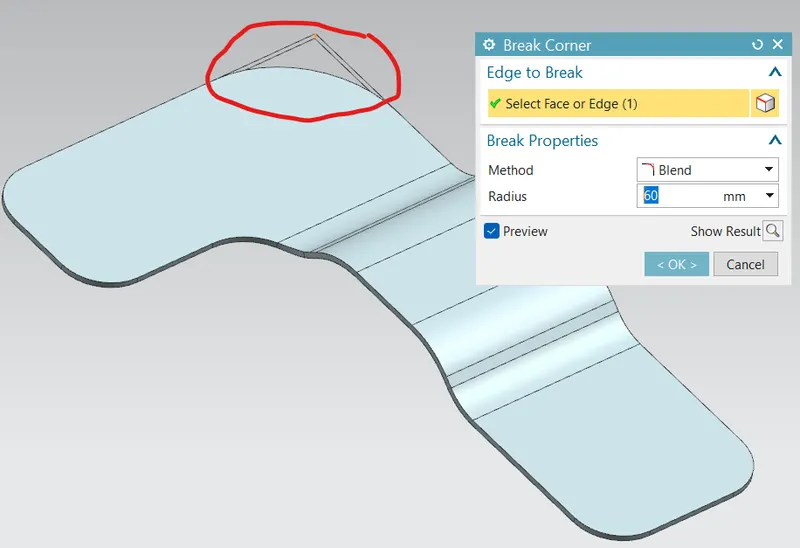
5. Remove all the sharp corners using break corner command.
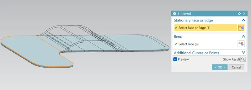
6. Unbend to add more features.
7. draw a line to add beads.
8. Rebend to previous structure.
9. Add some points on the specified position of the holes.
10. using hole command holes are added at the point.
Description:
- Contour Flange: Making a flangeof thickness 3mm of specific section as shown below;
- Normal Cutout: Removing unwanted material as drawn area shown below;
Break Corner: Removing the sharp corners
Unbend: Flattening the sheet metal by unbending all the bends.
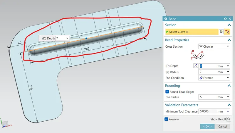
Bead: Adding a crcular sectioned bead with a line created on the flat surface.
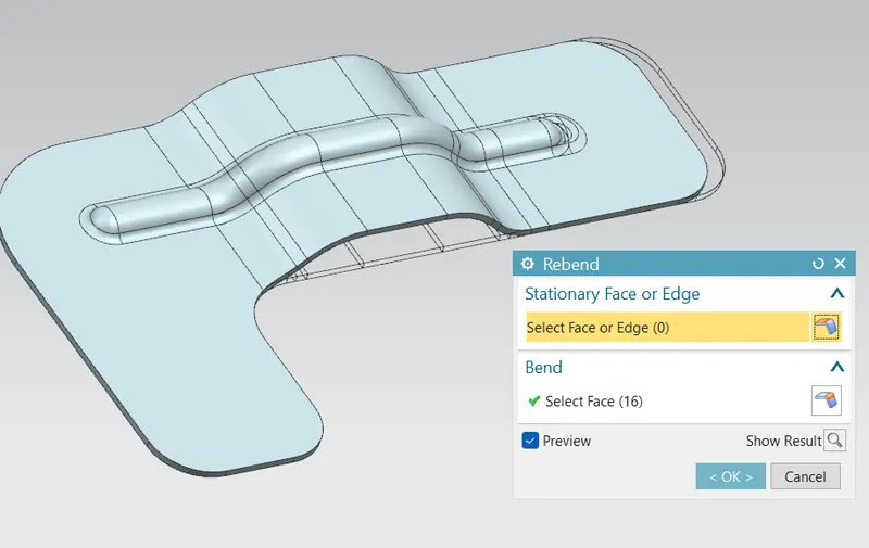
Rebend: Rebend to the previous shape.
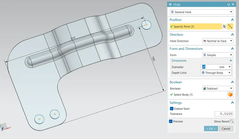
Hole: Adding holes at marked points in the sketch
Conclusion:
Bracket has been designed as per the drawing.
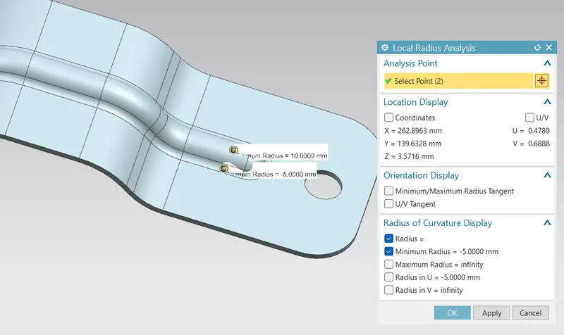
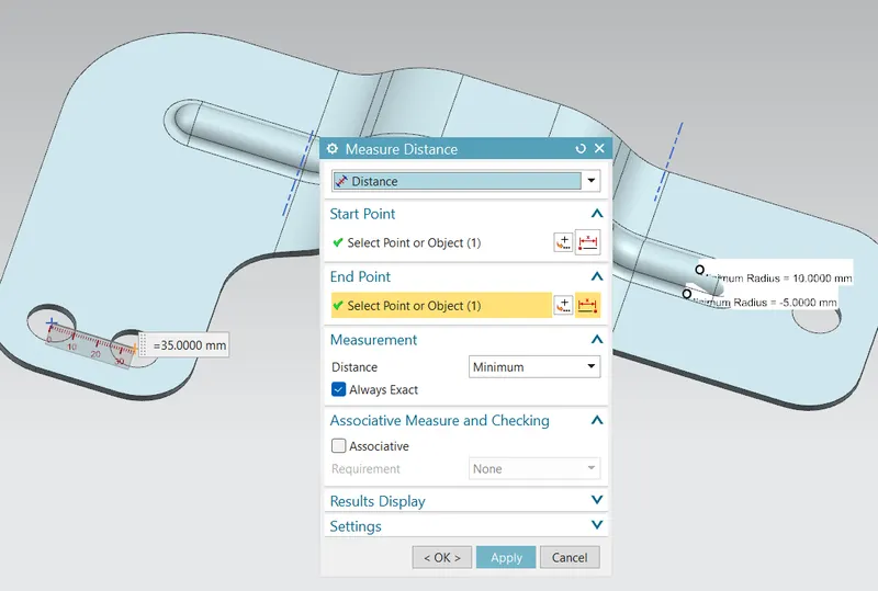
Local radius analysis:
Measuring distance b/w the two hole centers:
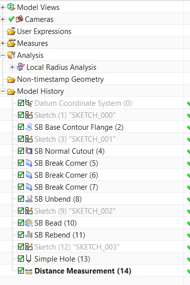
Model tree:
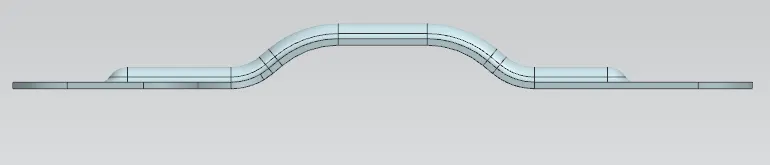
Front view:
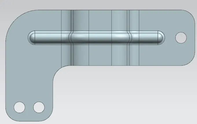
Top view:
Side view:
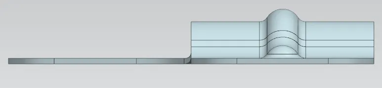
Isometric view:
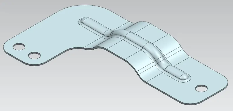
Drafting: