Advanced Sheet Metal Design Using NX Cad Challenge_6_Bracket
ADVANCED SHEETMETAL DESIGN OF BRACKET USING NXCAD
Objective: To create a bracket from 2D drawing using NX commands
Introduction:
Brackets is a support part for holding the components in an assembly. Generally all the brackets are made up of sheetmetal. Sheet metal parts are widely used in machinery, enclosure, brackets, and automobile due to its various advantages. The parts are normally manufactured with break press. Sheet metal is nothing but the thin sheets made from metal of size ranging from 0.5 to 6mm. In this project I used NX CAD tool for designing the sheet metal bracket. NX CAD is used as design tool in more than 85% of the sheet metal industries.
Design methodology:
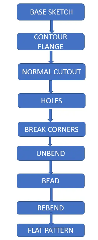
Features used:
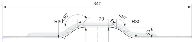
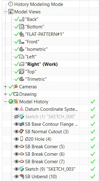
1. Sketch: In the XY plane draw the sketch as shown below using profile command in sketcher workbench
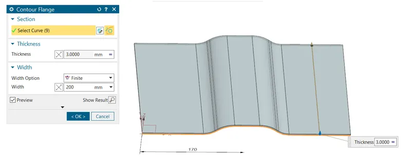
2. Contour Flange: Using the above sketch as reference, I have created the base using contour flange option. The width will be 200mm and thickness will be 3mm.
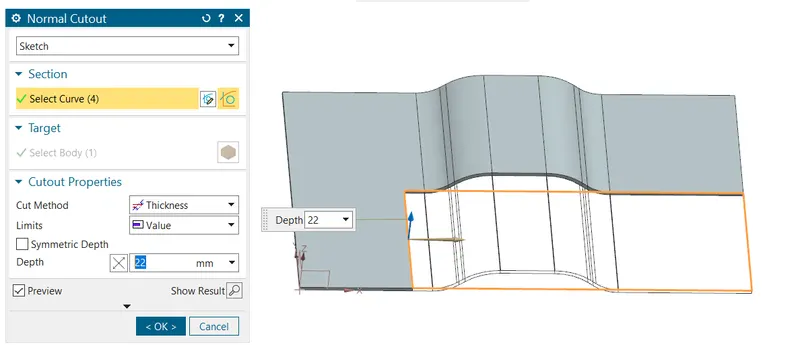
3. Normal cutout: Normal cutout is a command that is used to strip a piece of material from the blank. Here we are using normal cutout option to remove some material which is unnecessary.
4. Hole: Hole option is used to create holes. 20mm diameter hole is created.
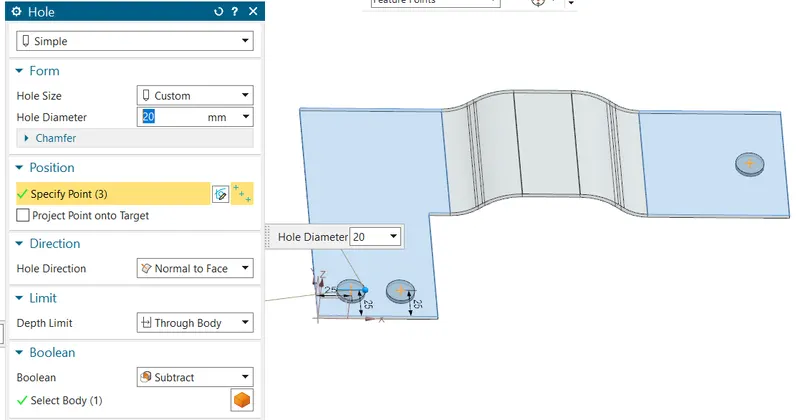
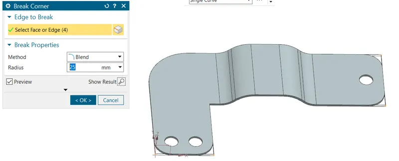
5. Break corner: Break corner option is used to create corner radii for sharp corners Here 60mm, 30mm and 25mm fillet radii are used.
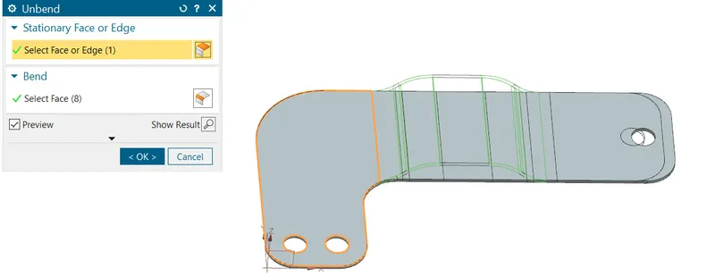
6. Unbend: Unbend the tab for creation of cutouts.
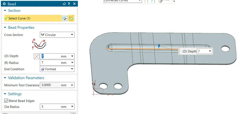
7. Bead: Bead is used to create emboss on the sheetmetal parts for strengtheneing purpose.
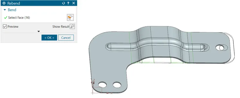
8. Rebend:
Rebend option is used to bring the bracket to original position after the creating the bead.
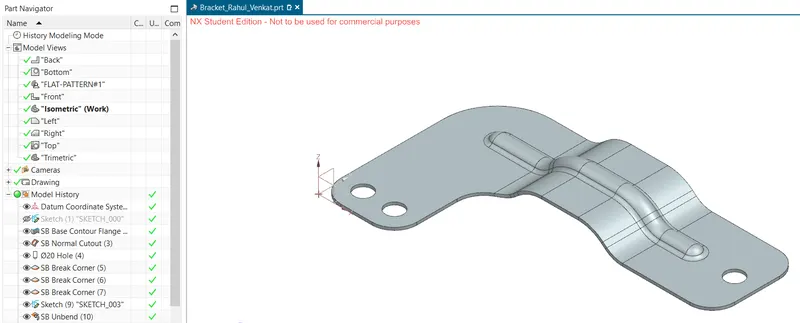
Orientations of BRACKET
Isometric view
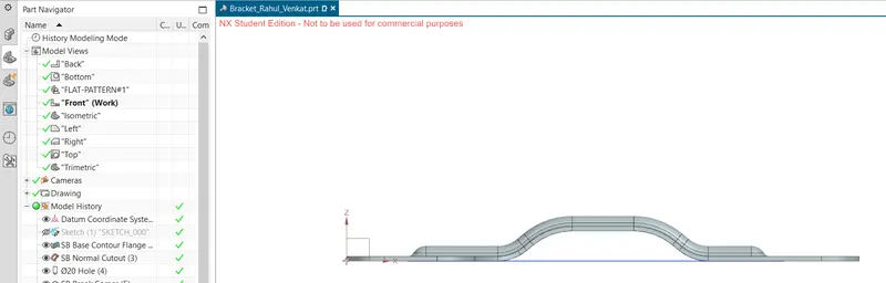
Front view
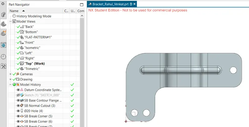
Top view
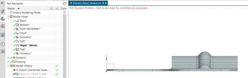
Side view
Model tree
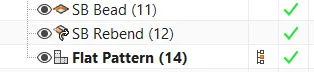
Flat pattern
Flat pattern is used to calculate the blank size
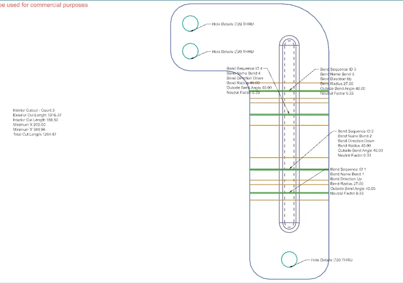
Drawing sheet
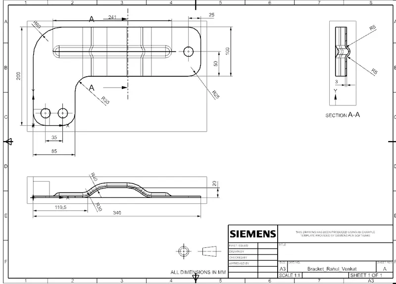
Conclusion: Thus, we have drawn bracket using NXCAD and created a drawing