Advanced Sheet Metal Design Using NX Cad Challenge_6_Bracket
Advanced Sheet Metal Design Using NX CAD _Bracket.
Objective
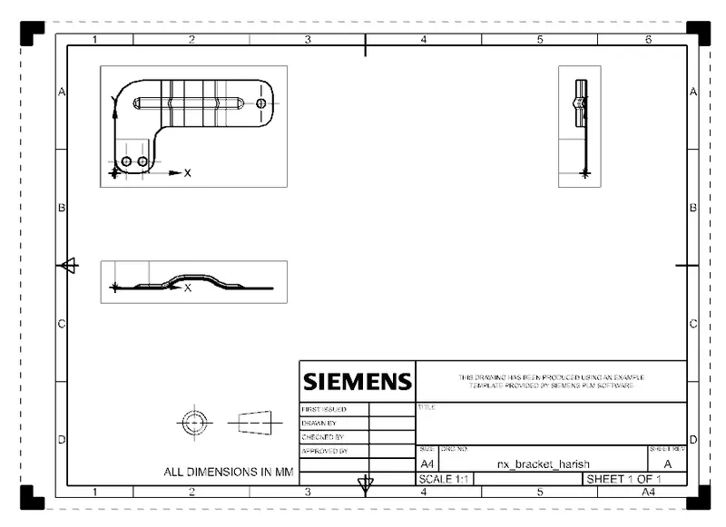
- To design a sheet metal Bracket in NX-CAD sheet metal application workbench and create the Bracket's drafting.
Introduction:
- NX sheet metal design software incorporates material and process information in sheet metal-specific modelling features: bends, flanges, tabs, cutouts, beads, dimples, louvres, corner and edge treatments, patterns and other formable features. We can also quickly convert solid models to sheet metal components and create sheet metal parts that enclose other components.
- With NX sheet metal CAD tools can apply standard values, such as material thicknesses and bend radii, based on industry or company best practices. With folding and unfolding capabilities, we can work with models at any stage of the fabrication process. NX sheet metal software creates accurate flat patterns for documentation and manufacturing.
Description
- Sketch the drawing for the Bracket in XZ Plane
Contour Flange:
- Creates a base feature by extruding a sketch along a vector, or adds material by sweeping a sketch along an edge or chain of edges
Normal Cut:
- Cuts material by projecting the sketch onto the model and then cutting perpendicular to the faces intersected by the projection.
Break Corner:
- Rounds or chamfers are sharp corners of a tab or a flange.
Unbend:
- Flattens a bend and the material adjacent to the bend.
Bead:
- Lifts material along the contour of a sketch that simulates a stamping tool.
Rebend:
- Restores an unbend feature to its previous bent state, along with any features added after the unbend feature.
Hole:
- Adds a hole to one or more solid bodies in a part or assembly with options of counterbored, countersunk and threaded
Flat Pattern:
- Creates a flat pattern feature from the formed sheet metal part.
View:
Front view

Top view
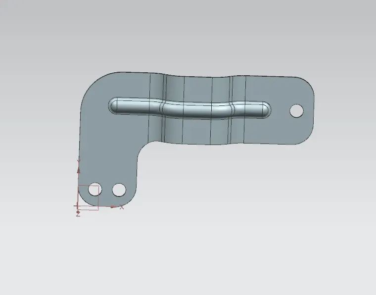
Side view
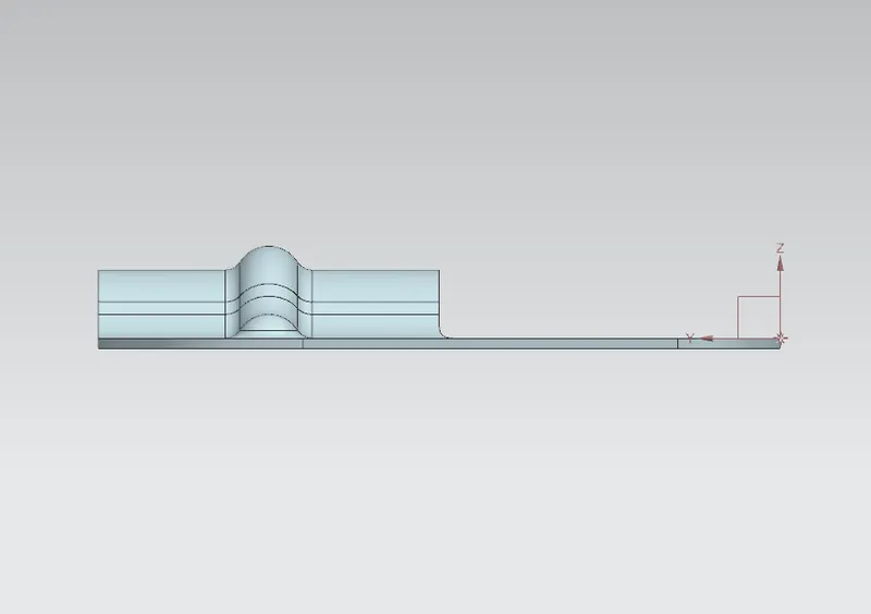
Isometric view
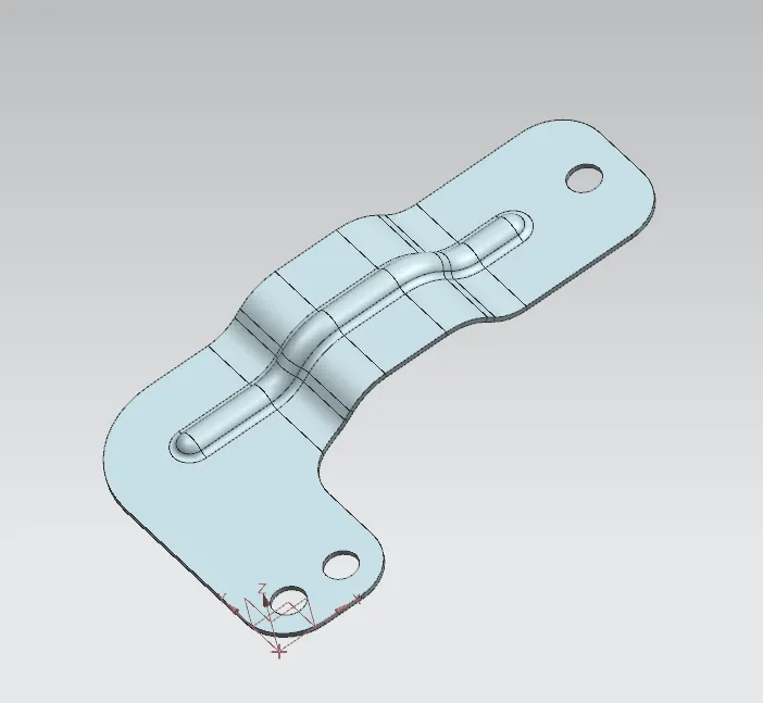
Flat pattern
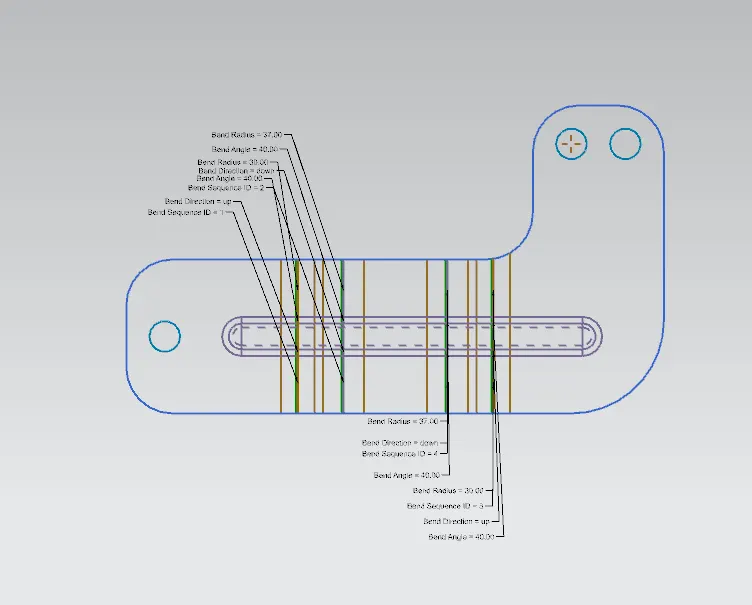
Drawing sheet
Conclusion
Thus, the sheet metal Bracket was built successfully with the inputs provided