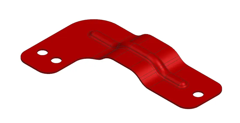
Advanced Sheet Metal Design Using NX Cad Challenge_6_Bracket
NX_Bracket
Aim:
To create Sheet Metal Component with Sheet Metal modelling tools applied throughout the modelling using NX.
Introduction:
In this we are going to create sheet metal Bracket step by step using seimens NX sheetmetal applicatiion.
Design methodology:
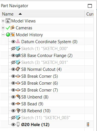
Procedure:
Step 1: Contour flange
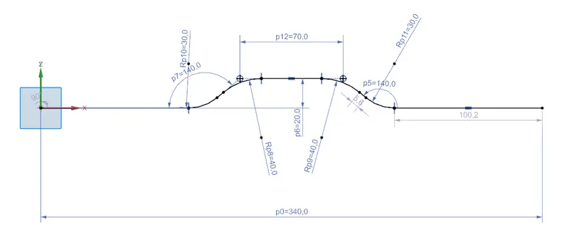
- Start Nx and create new file then the first step is to draw a sketch as shown and exit sketch.
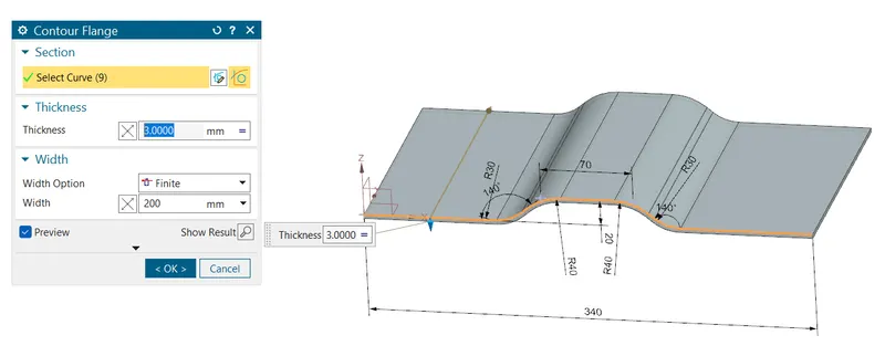
- Click on the button contour flange
 on the tab and select sketch give the value as shown.
Step 2: Normal cutout
- Click the button normal cutout from the tab
 and draw a sketch as shown then select the sketch for cutting out the material to obtain the shape.
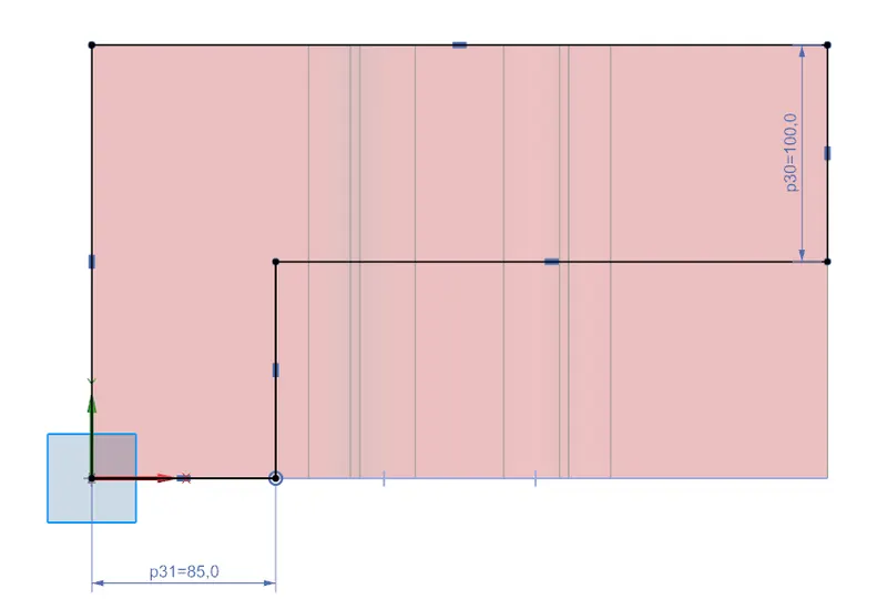
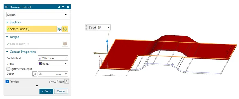
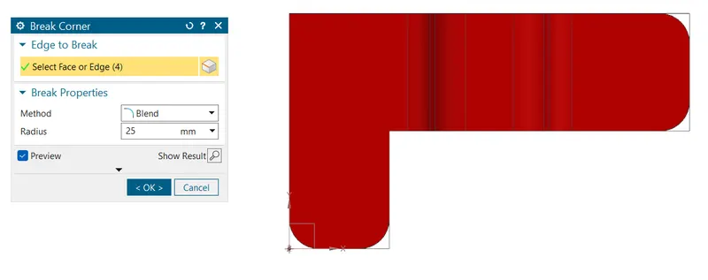
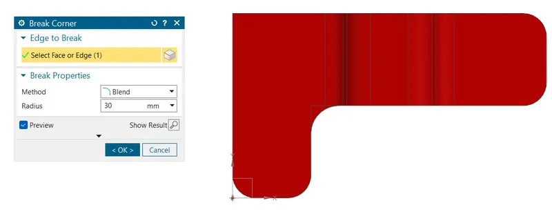
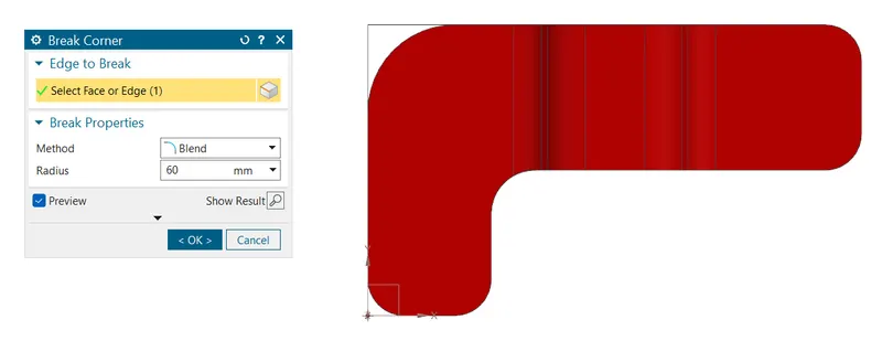
Step 3 : Break corner
 We need to give three types of radius for different edges R25, R30, R60 as shown step by step.
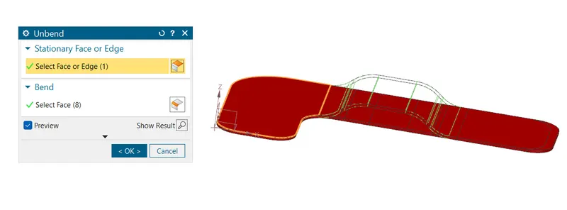
Step 4 : Unbend
- Select the button
 and click the face which is need to be base and give the rest to unbend as shown.
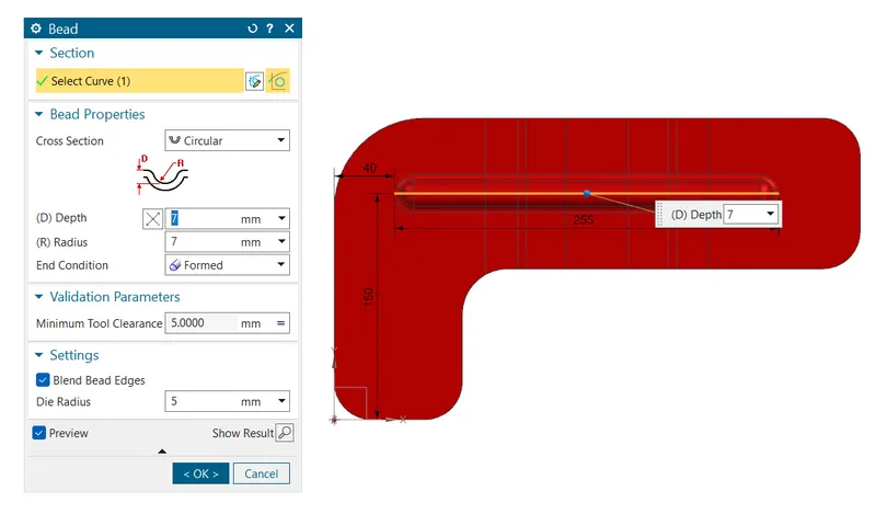
Step 5 : Beads
- Click on the bead button from the more option in punch then sketch line and give the value as shown.
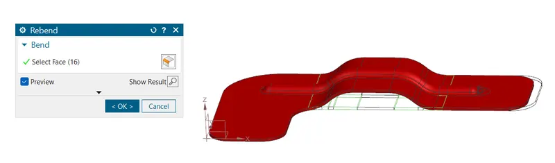
Step 6 : Rebend
- Rebend the faces by selecting them in reverse order in which they were bend as shown.
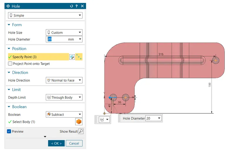
Step 7 : Hole
- After rebending the sheet add features such as holes as shown get the feature from command finder by typing hole.
- Then sketch the point for hole position and select these points for the hole position.
Result: Drafting
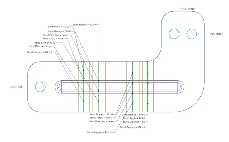
- Go for drafting ctrl + shift + D as shortcut a window will pop-up then give paper size and select the flat pattern as view in base view .
- Then delete the unwanted text generated along with it you can also give further dimensions and print them if need.
Model view:
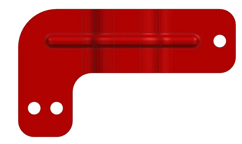
Top view
Front view
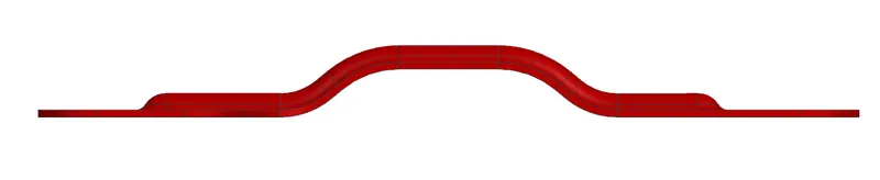
Right view
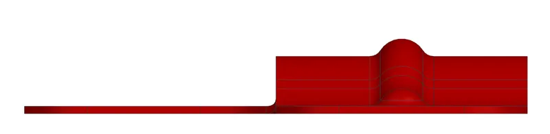
Isometric view