Advanced Sheet Metal Design Using NX Cad Challenge_6_Bracket
Design of creating a Bracket in NX
Objective
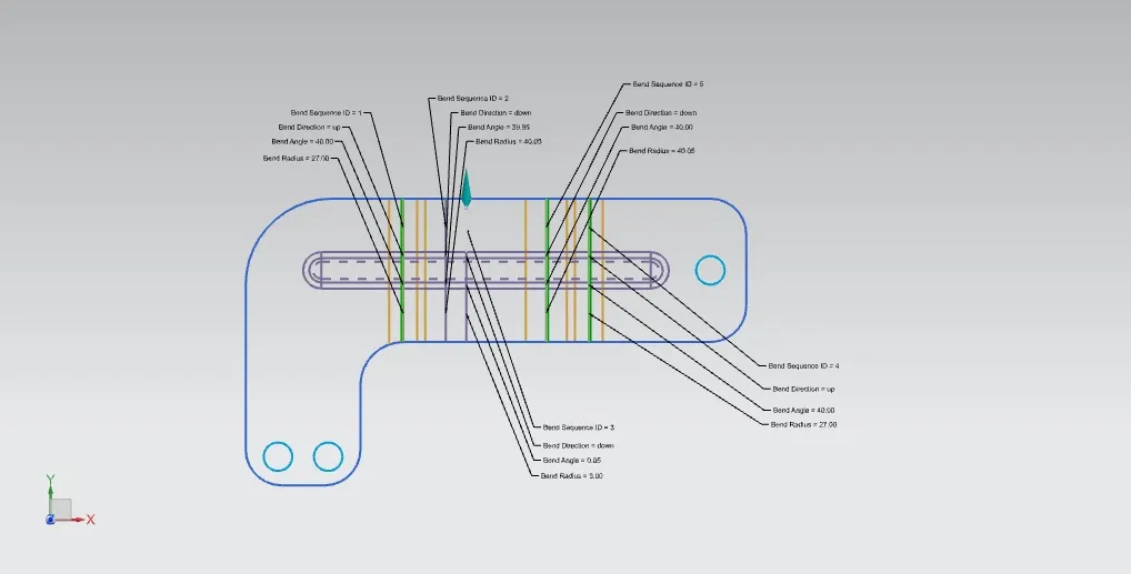
Our aim is to create a bracket from the given 2D drawing in 3D view for uniform thickness.
Introduction
In NX environment we are going to create a bracket from the given 2D drawing using nx command like contour flange, normal cut out, break corner and creating bead over it.
Design Methodology
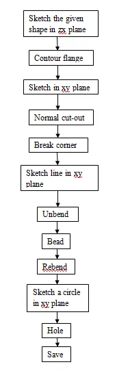
Explanation of commands
Contour flange
It is another type of creating a flange by extruding a sketch along a vector (axis) at a required distance or length.
Normal cut-out
Sketch the required shape on a base or at any sheet metal and it will remove or cut the shape which is drawn on the base and shows the remaining base or it can be reversed.
Breaking corners
It is applied to sharp edges to break the corner where it is required and it has bend, chamfer type and it can make a corner at required radius.
Hole
It is used to create a hole on metal and it has different type of hole like general, screw clearance, drill etc..direction of holes can be changed, form and dimension can be applied to obtained the required shape.
Beads
It lift the material along the sketch with different cross section like circular, U and V shape at required depth, radius with end condition like formed, punched etc.
Unbend and Rebend
It is used to flatten the bodies to add some more features and then rebend to its original position.
Modelling views
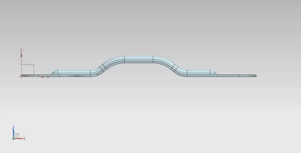
Front view
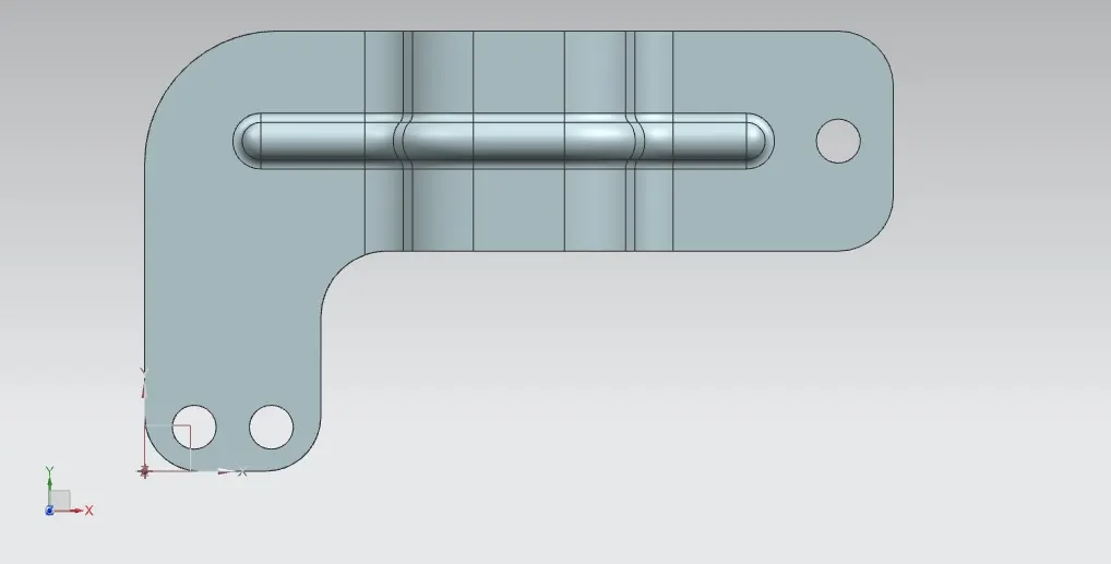
Top view
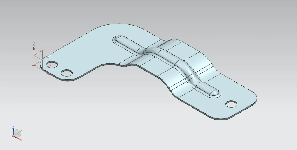
Isometric view
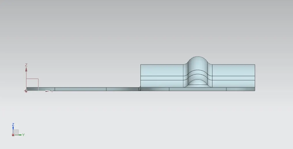
Side view
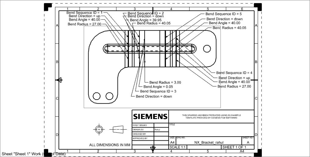
Drawing sheet
Conclusion
Thus the bracket has been successfully created from the given 2D drawing.