Advanced Sheet Metal Design Using NX Cad Challenge_2_Box Assembly
Design of Box using sheet meta Applicationl in NX
Objectives
Our aim is to design a box in sheet metal application in NX using nx commands like tab, flange, hem flange, mirror body, mirror feature, closed corner, unite, dimple, beads, break corner and normal cut out.
Introduction
To design a box in nx using commands, first we need to select the sheet metal application and giving the required preferences for the model which will be the global valve though out the model if required it can also be changed and then we need to select the plane to be sketched.
Once the required unit is selected it can’t be changed during the modelling.
Design methodology
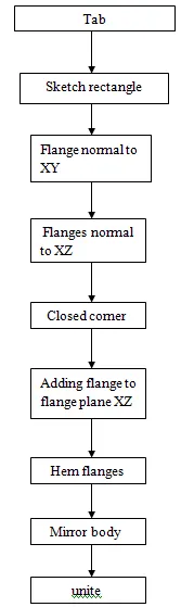
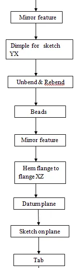
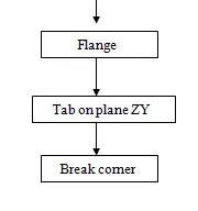
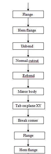
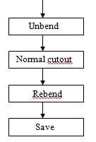
Explanation of commands:
Tab
By using tab we create base on plane of a required thickness from which other component will be added to it.
Flange
We create a flange with the edges of base (tab) of required length, direction and in any angle with material inside or outside and with bend radius.
Hem flange
It is a type of a flange add at the edge of flange or base which will be folded over itself with a different type of folding option like open loop, closed, s type etc.. with bending inside or outside at required radius.
Mirror body
This feature is used to mirror or copy the body on another plane w.r.t orginal body, first select the body and then the plane to be mirrored.
Unite
It is used join or combine two or more body in to single one for other commands can be added or if it is required.
Dimple
It is used to lift the required area of a model created on a plane in upward or downward direction at required depth, side angle and material inside or outside at a required radius.
Mirror feature
It used to create same model or sketch on another plane by selecting the required sketch and the axis.
Beads
It lift the material along the sketch with different cross section like circular, U and V shape at required depth, radius with end condition like formed, punched etc.
Breaking corners
It is applied to sharp edges to break the corner where it is required and it has bend, chamfer type and it can make a corner at required radius.
Bend
Bend is used to bend the required metal by sketch a line on a base or any and by selecting the stationary face and select the line to be bend, mention the angle as well as we can change direction and side of bending and giving radius to it.
Normal cut-out
Sketch the required shape on a base or at any sheet metal and it will remove or cut the shape which is drawn on the base and shows the remaining base or it can be reversed.
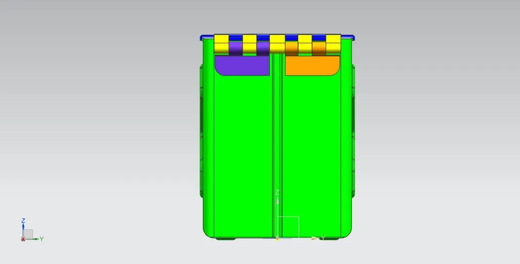
Model views
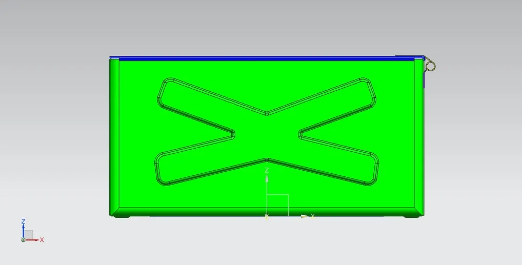
Front view
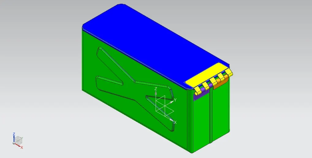
Isometric View
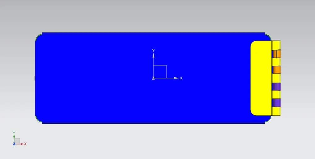
Top view
Side view
Conclusion
Thus modelling of box has been designed according to the given model with a different types of its views.