Advanced Sheet Metal Design Using NX Cad Challenge_6_Bracket
Points to be followed in report
- Title of the Project
- Objective
- Introduction
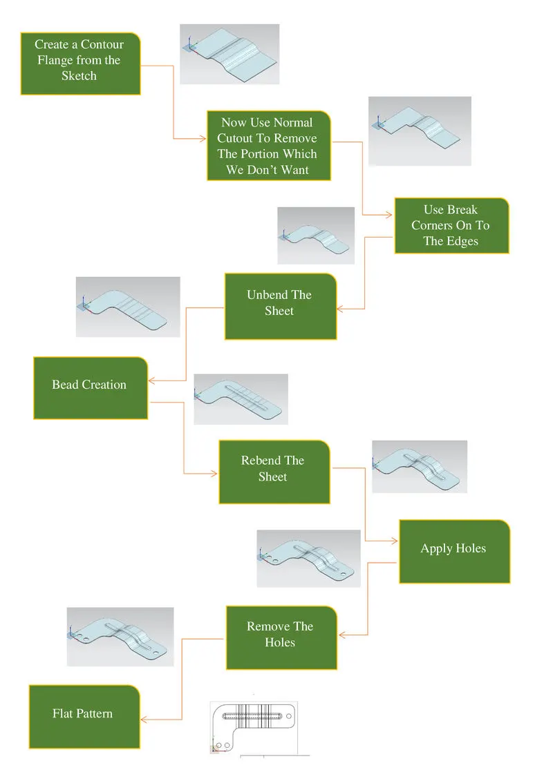
- Design methodology / approach (To be explained with the help of Flowcharts only)
- Description (Need to explain tools/ Features used while designing)
- Upload a min of four screenshots of Model in the report. (Front View, Side View, Isometric View and the Top View)
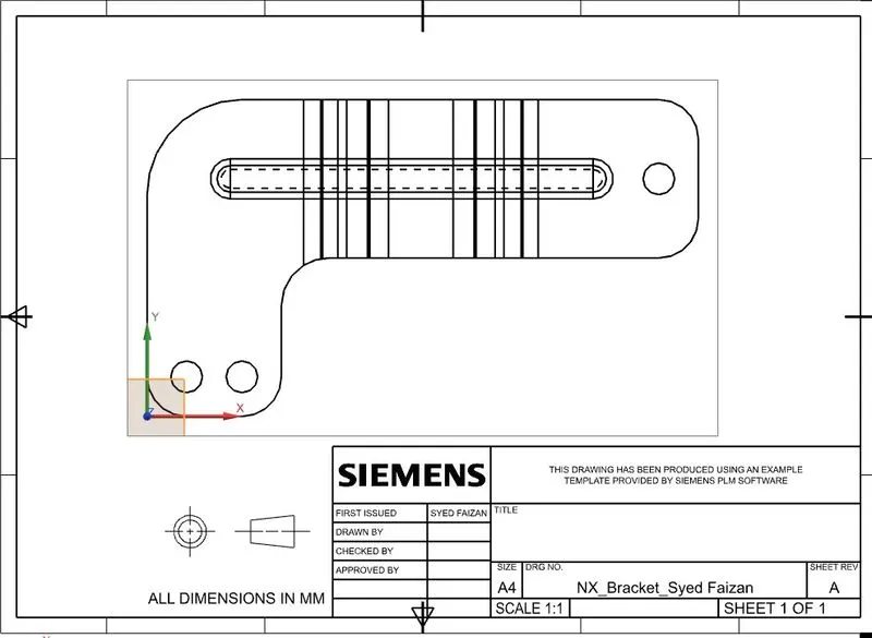
- Attach Detailed Drawing Sheet Image (If Required)
- Conclusion
Title of the project:- Advanced Sheet Metal Design Using NX Cad Challenge_6_Bracket
- Open new sheet metal part in NX cad
- Create contour flange using sketch with given parameters
- Cut the body using normal using given dimensions
- Give some break corners with required dimensions
- Unbend the model and create bead with using line sketch
- Create some holes as per requirements
- Rebend the model
- If required create the drawing sheet using draft tool for understanding to customer
- Hence the model is ready
Description :
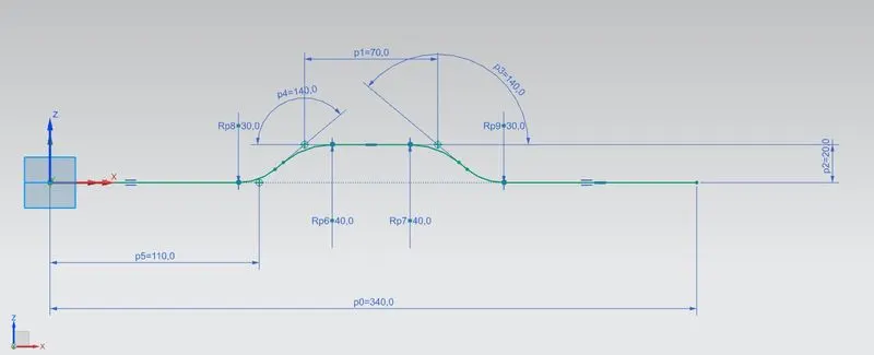
Create the base sketch from reference to the given bracket sketch. Create the sketch profile as shown in the below picture
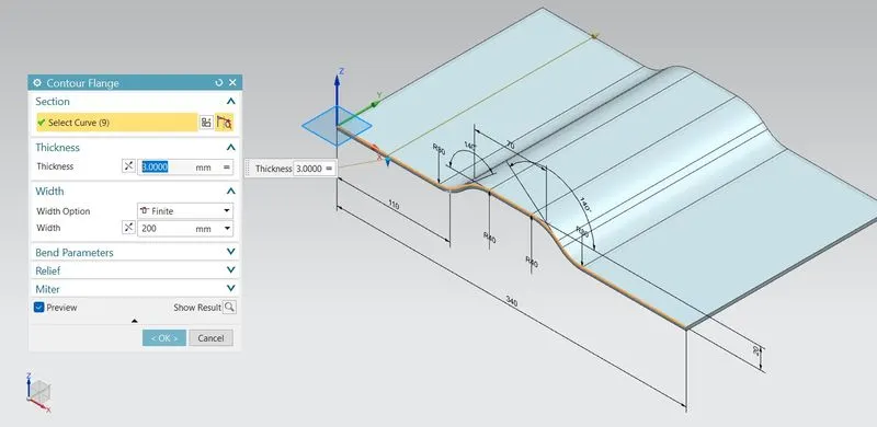
By using contour flange, create the base to a length of 200 mm
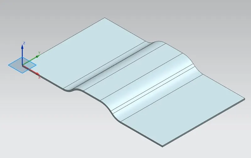
Create a sketch on top plane as shown in figure
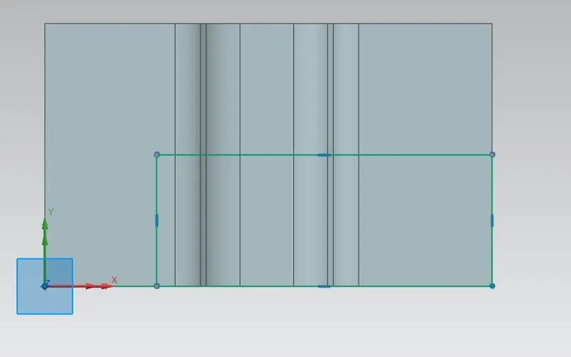
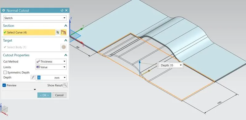
Create the normal cut out from the drawn profile
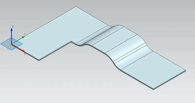
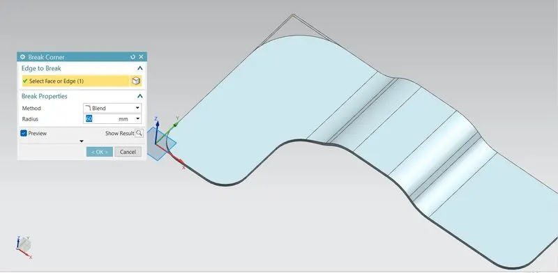
Smoothen the sharp corners using break corner option with a radius values of 25 mm
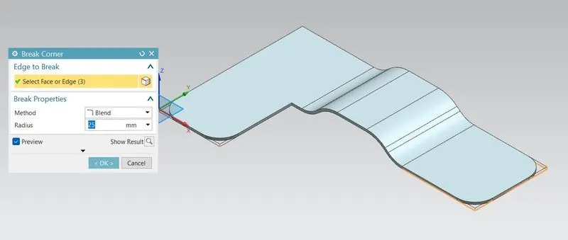
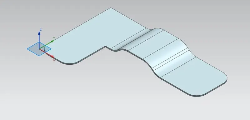
Break corner using radius 30 mm

Break corner using 60 mm radius
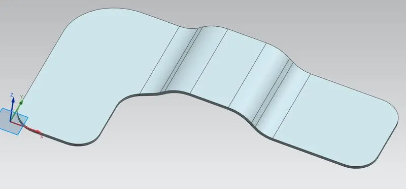
Unbend:
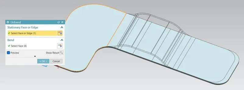
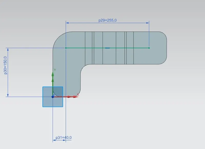
Create sketch for bead
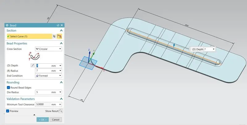
Create bead form the profile created
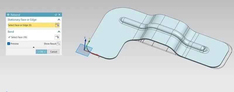
Rebend the bracket
Create a points on top view to locate the holes
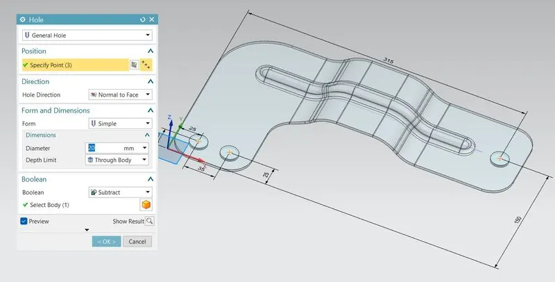
Pattern:
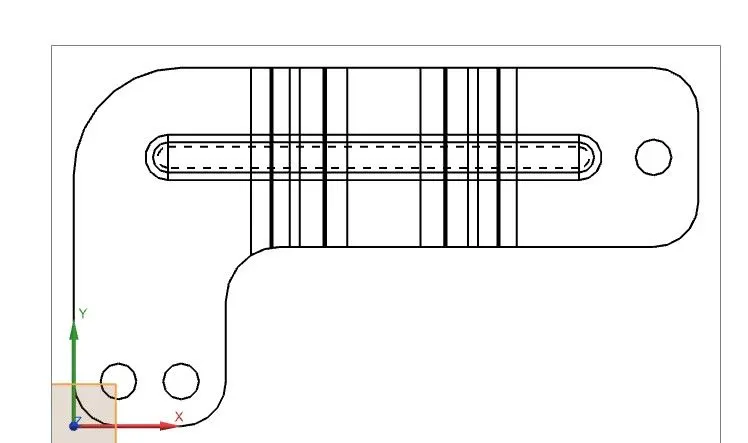
Diffrent Views :
- ISOMETRIC VIEW:--

- FRONT VIEW:--
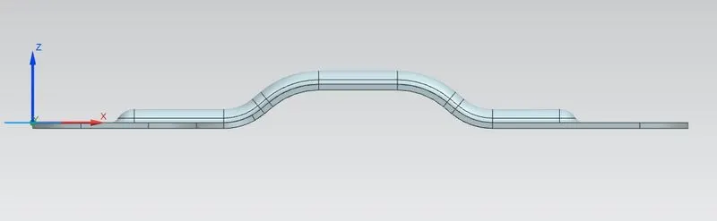
- SIDE VIEW:--
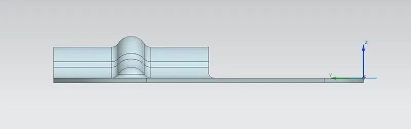
- TOP VIEW:--
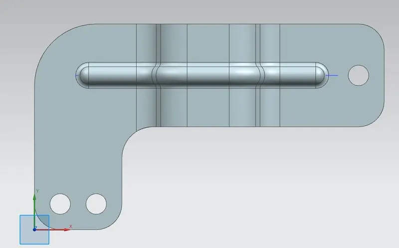
Drafting Sheet:
Conclusion :
Bracket is created is using advanced sheet metal tools in NX CAD.