Advanced Sheet Metal Design Using NX Cad Challenge_6_Bracket
DESIGN OF BRACKET USING SIEMENS NX SHEET METAL APPLICATION
Objective:
The objective is to create a sheet metal bracket by studying the given 2d drawing sheet using NX sheet metal features such as contour flange, hole, bead, normal cutout, unbend & rebend, etc.
Introduction: Sheet Metal Bracket brackets are used for keeping the machine parts supported and protected. But nowadays, the application of stents is extremely extensive, which can be encountered everywhere in work and life, such as tripods for cameras, cardiac stents used in the medical field, etc Sheet metal is metal formed by an industrial process into thin, flat pieces. It is one of the fundamental forms used in metalworking, and we can obtain varieties of shapes using a wide range of processes, tools, etc. Sheet metals are available in flat pieces and coiled strips with thicknesses varying from 0.1mm to 10mm.
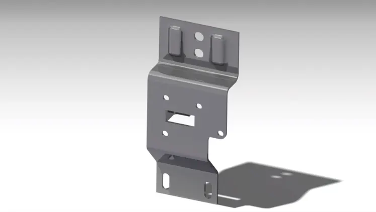
Design methodology:
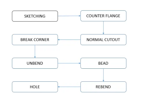
Description
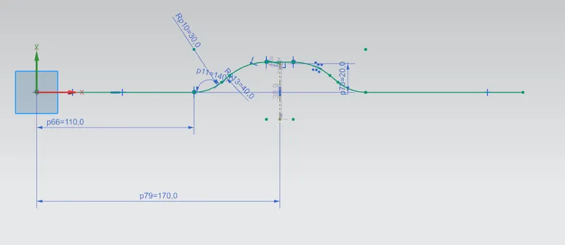
Sketch - It is used to create a 2D sketch. Here, it used to create a Contour flange then been and the to create Holes
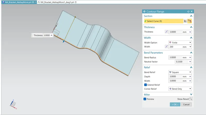
Contour Flange -It used to create the base feature or secondary feature of a sheet metal part by extruding a sketch created along a particular vector
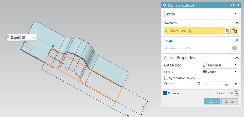
Normal Cutout - With this tool we can remove some portion of the sheet metal part by creating or projecting a sketch into the particular face of the part.
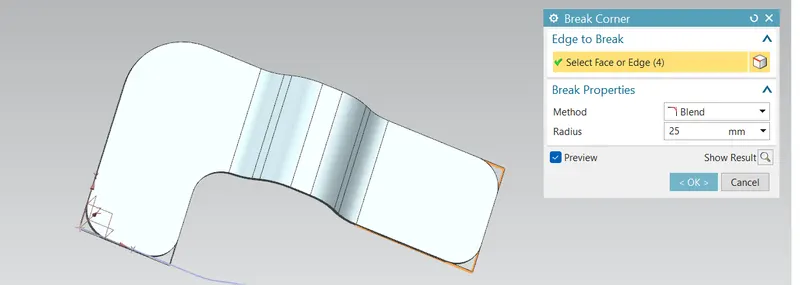
Break Corner - It used to give fillet or chamfer to the sharp corners of the sheet metal part
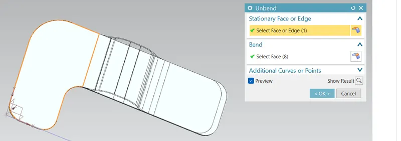
Unbend - Used to flatten the sheet metal part in order to create some complex feature on the sheet metal part which is not possible to create in it\'s original position.
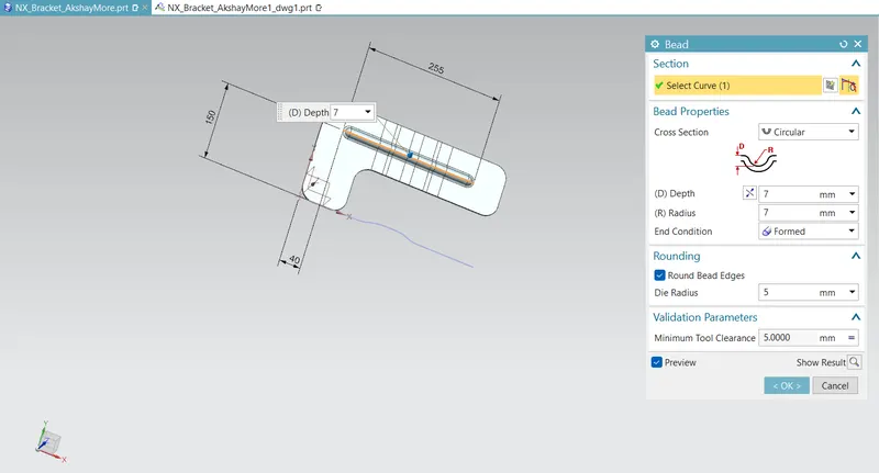
Bead - It used to create emboss over the sheet metal part from an open loop/closee loop sketch created over that particular face/plane in order to increase strength locally
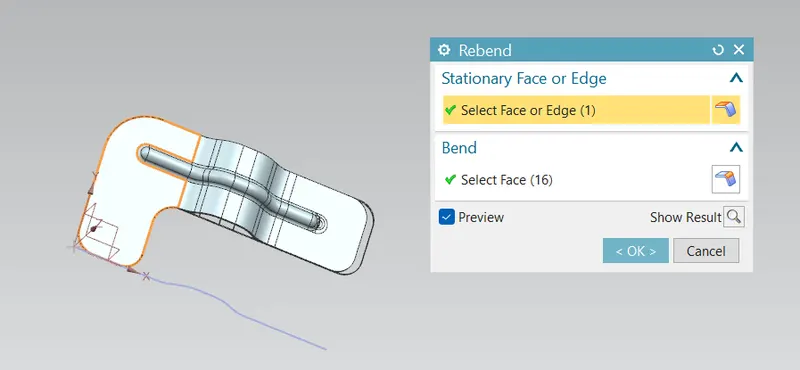
Rebend - It used in ordeer to get back part in its original position
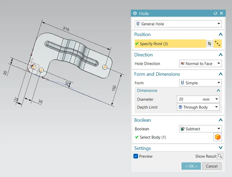
Holes - Holes can be created ont the sheet metal part by specifying point os the face of the part by using a sketch tool
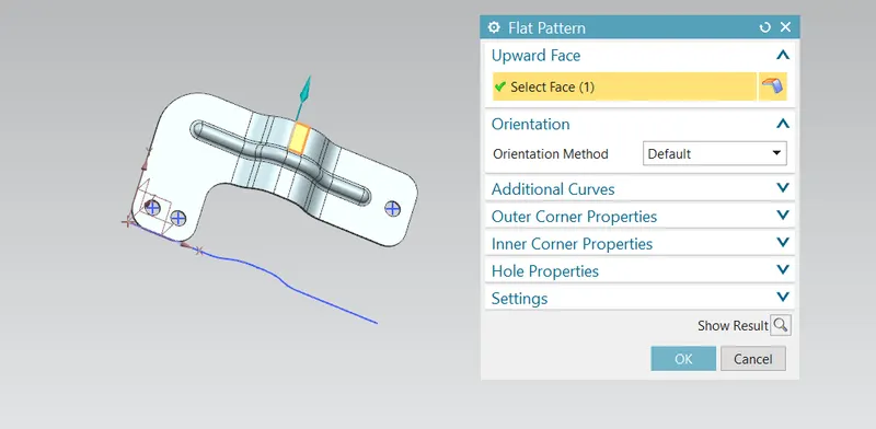
Flat Pattern
A flat pattern is the shape of the sheet metal part before it is formed. Use this to create drawings for manufacturing. Flat patterns show bend lines, bend zones, center lines, and the shape of the entire sheet metal body with all bends flattened and bend factors considered.
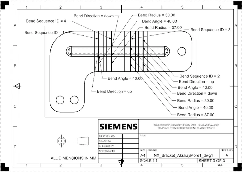
Drawing View
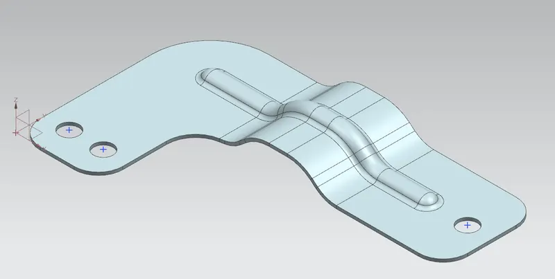
Isometric View
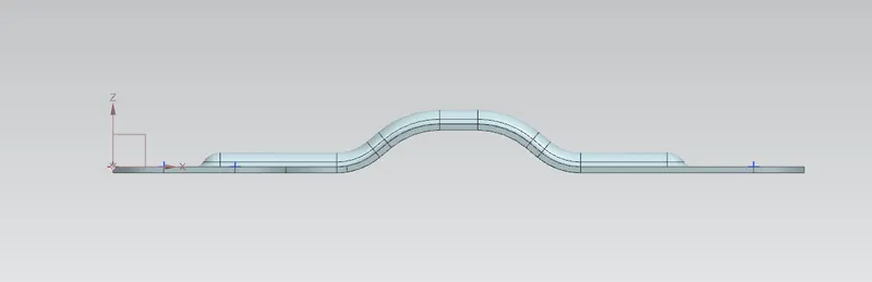
Front view
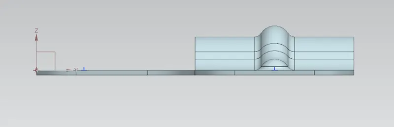
Side view
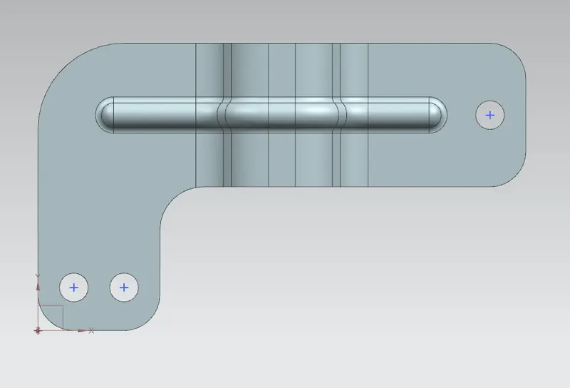
Top view
Conclusion - Using various tools of the NX sheet metal work bench we have completed the design of the Sheet metal bracket