Advanced Sheet Metal Design Using NX Cad Challenge_6_Bracket
Write a detailed report on the Sheet Metal Component with a good explanation of Sheet Metal modeling tools applied throughout the modeling. Also, attach the Final model Images (Min. 4 images) of the Sheet Metal Bracket.
Advanced Sheet Metal Design Using NX Cad Challenge_6_Bracket
The sheets are made from different kinds of metals such as aluminum, brass, copper, steel, tin, nickel, and titanium. The sheet’s thickness depends on the material needed for a project. Thicknesses can vary from 0.15 -6.00 mm significantly; extremely thin sheets are considered foil or leaf, and pieces thicker than 6 mm (0.25 in) are considered plate steel or “structural steel.”
SHEET METAL DESIGN: NX sheet metal Design provides the design professional with a complete set of tools to efficiently create and manage sheet metal parts based on the knowledge of material properties and manufacturing processes. NX sheet metal design tools incorporate material and bending information, enabling the model to represent both the formed component and flatten blank shapes.
DESIGN METHODOLOGY:
- creating the new sheet metal part in nx cad
- then creating the sketch on xz plane with given dia
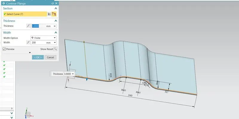
- used the sketch as a reference contour flange is created
- after that creating the sketch on the top of the flange
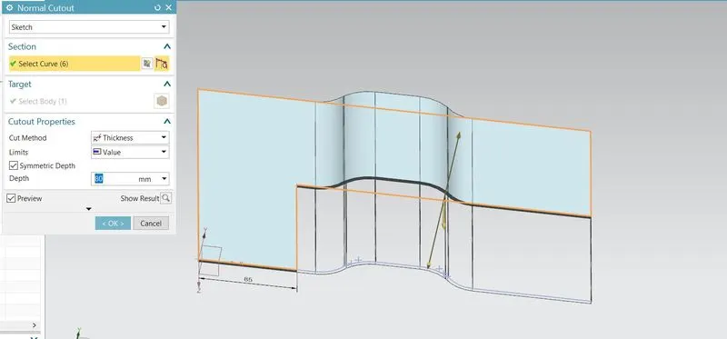
- using normal cutout with the sketch as a reference
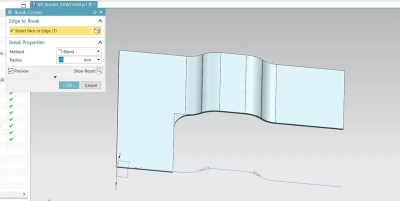
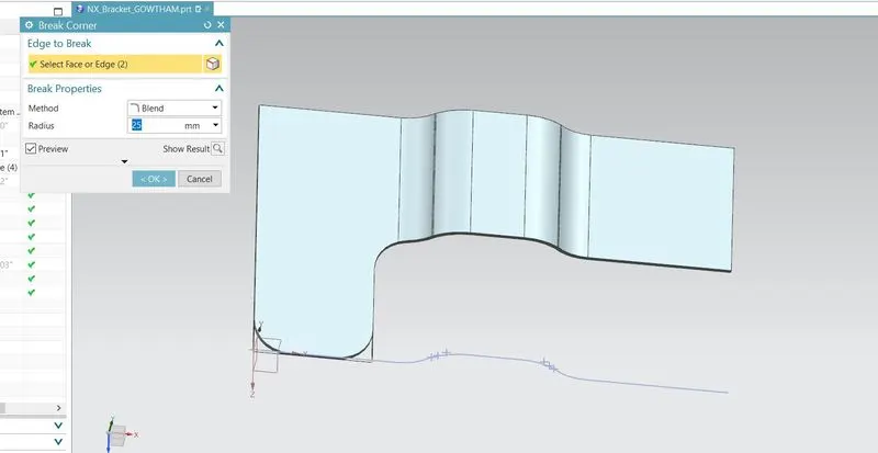
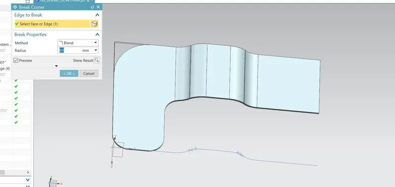
- break corner is used in three places to get a smooth surface
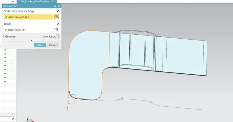
- unbend the surface to creat bead
- creating the sketch on top xy plane
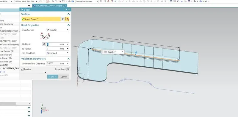
- with reference from the sketch bead is created
- after creating bead rebend the sheet metal
- creating the points on xy axis
- pointed are converted into holes with help of the hole command
- sample measurements are taken to check holes are located in the correct place
- 2D drafting is created for this model
FLOW CHART VIEW
STARING NX WITH SHEET METAL

CONTOUR FLANGE CREATION
NORMAL CUT-OUT AND BRACK CORNER USED
UNBEND, BEADS CREATION & REBEND PERFORMED
HOLES CREATED ON TOP
DRAFTING CREATED (2D)
Description :
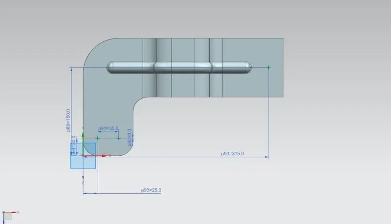
Create the base sketch from reference to the given bracket sketch. Create the sketch profile as shown in the below picture
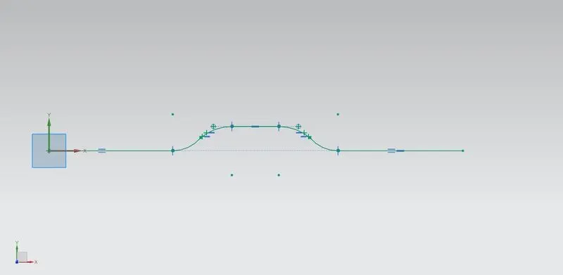
THE CONTOUR FLANGE COMMAND IS USED TO CREATE THE SURFACE WITH A THICKNESS OF 3 MM IMAGE IS SHOWN BELLOW
SKETCH IS CREATED TO PERFORM NORMAL CUTOUT COMMAND AND REFERENCE IMAGE IS SHOWN BELLOW
BREAK CORNER OPTION IS UESED TO GET RIP OF CORNER INTO SMOOTH SURFACE AND IMAGE IS SHOWN BELLOW
UNBEND COMAND IS USED TO CHECK WHETHER THE SURFACE IS UNBENT TO MANUFACTURE
BEAD IS CREATED WITH THE REFERENCE OF SKETCH DEPTH 7 MM AND RADIUS OF 7MM
REBEND IS DOWN AFTER THE BEAD IS CREATED AT THE TOP OF THE SURFACE AND A POINT IS CREATED TO PERFORM THE HOLE
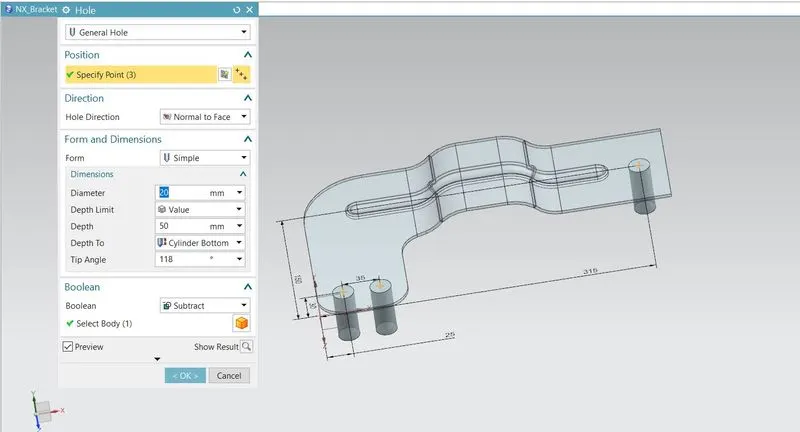
HELE COMMAND IS USED WITH THE DIMENSIONS OF 20 DEPTH LIMIT OF THROUGH BODY
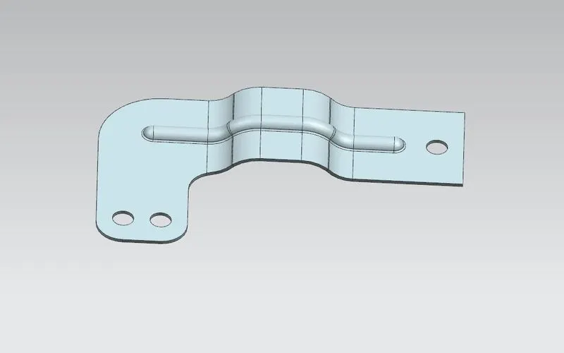
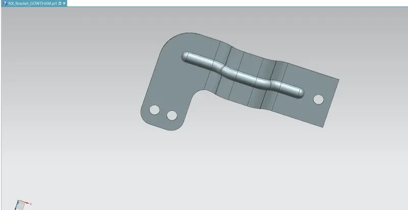
SMAPLE IMAGE
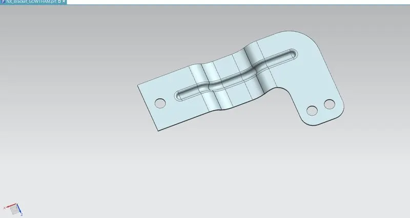
2D SKETCH IS CREATED AND SHOWN BELLOW
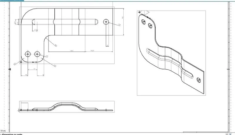
Conclusion :
The bracket is created with the help of NX CAD software and advanced sheet metal tools are used to create this model