Advanced Sheet Metal Design Using NX Cad Challenge_6_Bracket
Title :- Bracket design
Objective :- Design a Bracket useing UGNX design software.
Introduction :- Bracket is a sheet metal component, Which is used in manufactruring industries and
Automobile industries extensively.
:- Commanly Bracket consisr of holes and as well as Bending profiles also.
:- Bracket is commny used for holding purpose and for many more uses.
Design approach flow chart :-
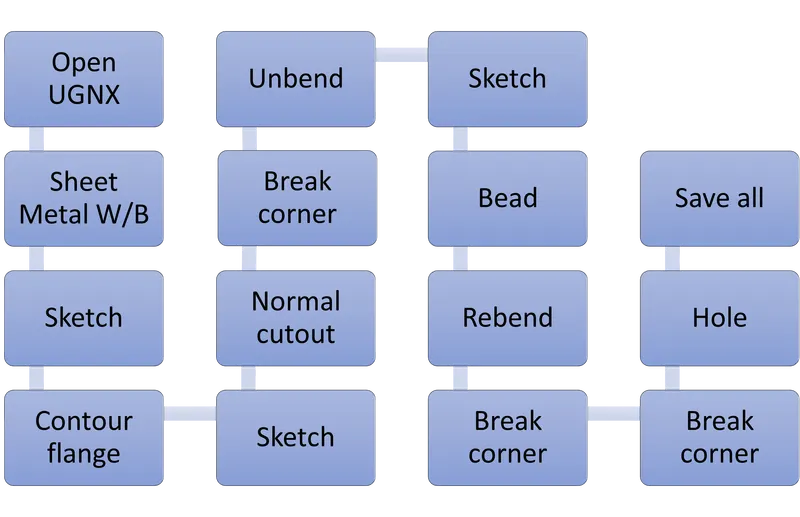
Description
* Sketch :- Created a sketch with respect to Z,X Direction as per given dimensions.
* Contour flange :- Creat contour flanges 300 mm width.
* Sketch :- Created a sketch to remove outside material.
* Normal cutout :- Apply normal cutout to remove outside material using last drawn sketch.
* Break corner :- Break corner by applying Radius 30 mm.
* Unbend :- Apply unbend to all.
* Sketch :- Created a sketch to apply bead.
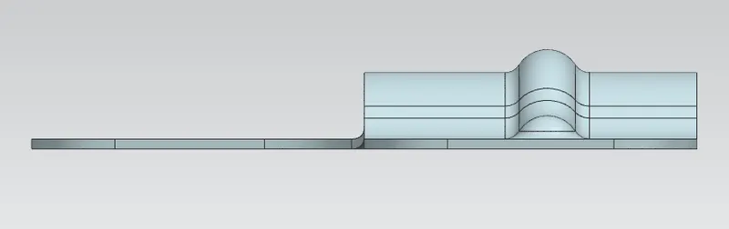
* Bead :- Creat bead of Radius 7 and depth 7 mm.
* Rebend :- Apply Rebend to unbended corners.
* Break corner :- Break four corners by applying Radius 25 mm.
* Break corner :- Break one corner by applying Radius 60 mm.
* Sketch :- Sketch a circle of diameter 10 mm for bead operation.
* Hole :- Use hole command and select simple and select radius point and apply 20 mm Dia hole.
* Save all :- Save all.
Model Screenshots
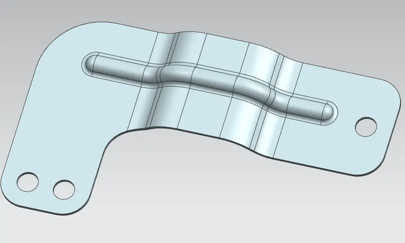
Isomatric view
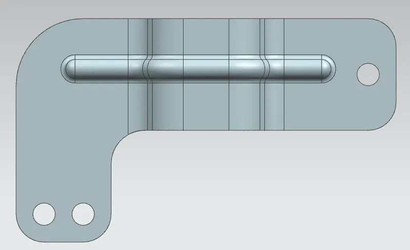
Top view
Front view
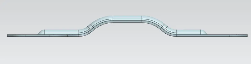
Side view
Conclusion :- I would like to conclued this, iam able to design any kind of Barckets as per drawings
and as well as without dimensions based on application and concept.