Advanced Sheet Metal Design Using NX Cad Challenge_6_Bracket
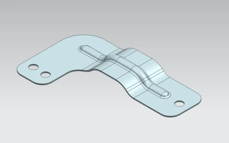
BRACKET
Objective:
To design a sheet metal bracket using NX CAD.
Introduction:
- It is a robust 3D solution that provides fast and realistic concept design and modeling.
- Superior in power and flexibility.
- NX CAD design tools are setting new standards for speed performance and ease of use.
- It supports modeling of complex surfaces, solids and advanced free form modeling (Sheet Metal).
- It is also known as Unigraphics.
Design Methodology:
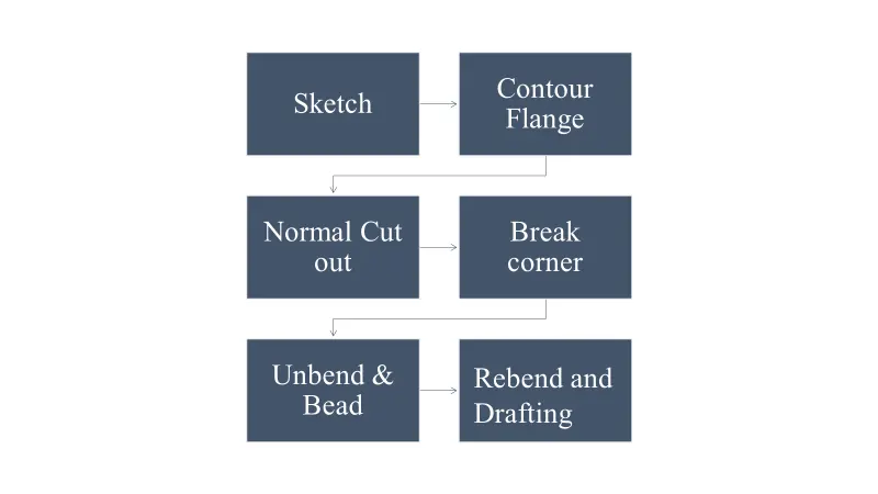
Description:
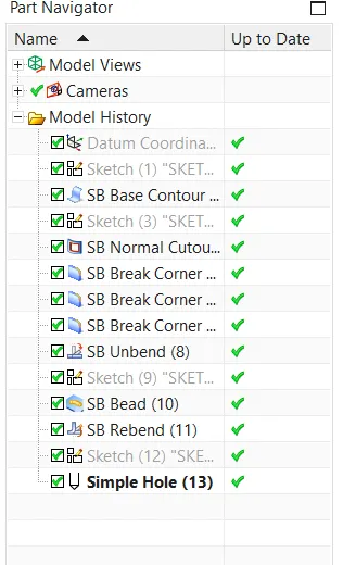
Commands used while designing a sheet metal bracket are as follows.
- Contour flange
- Normal cutout
- Break corner
- Unbend
- Bead
- Rebend
- Simple hole
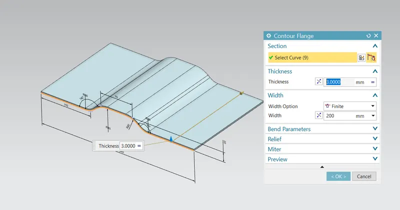
Contour flange:
Creates a base feature by extruding a sketch along a vector or adds a material by sweeping a sketch along an edge or chain of edges.
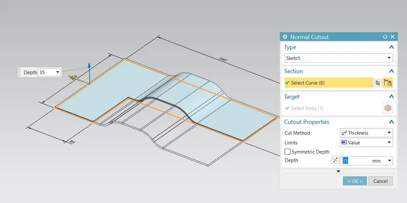
2. Normal cutout:
Cuts a material by projecting a sketch on to the model and then cutting perpendicular to the faces intersected by the projection.
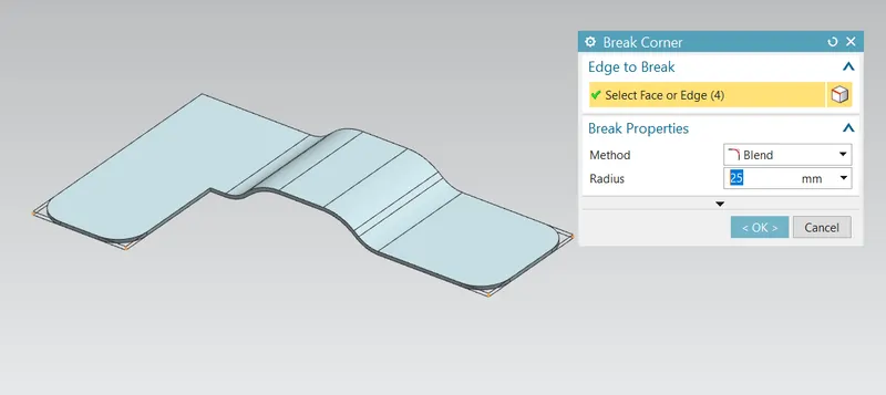
3. Break corner:
Rounds or chamfers a sharp corner of tab or flange.
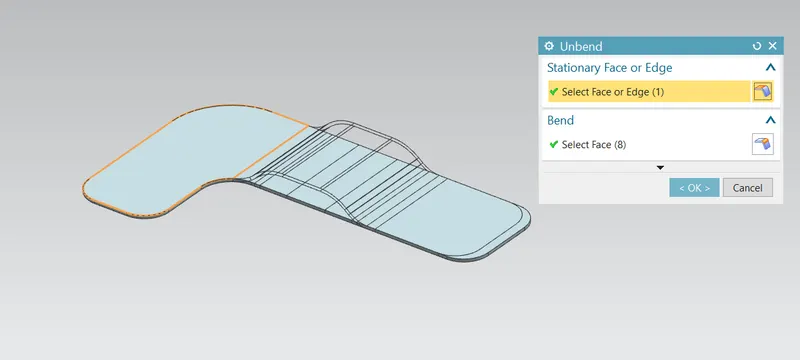
4. Unbend:
Flattens a bend and the material adjacent to the bend.
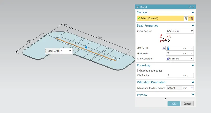
5. Bead:
Lifts material along contour of a sketch that simulates a stamping tool.
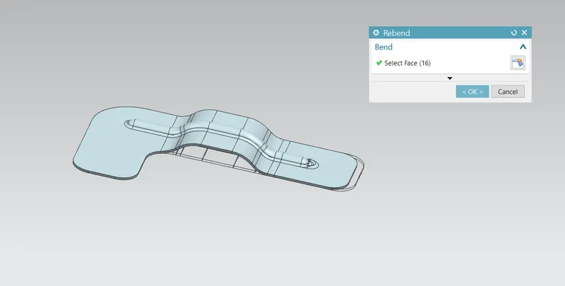
6. Rebend:
Restores an unbend feature to its previous bend state along with any features added after the unbend feature.
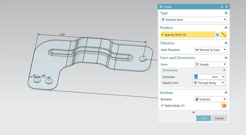
7. Simple hole:
Adds a hole to one or more sheet metal/solid bodies in a part or assembly for counterbored, countersunk and threaded.
Create a sketch for contour flange with line and arc as shown in figure.
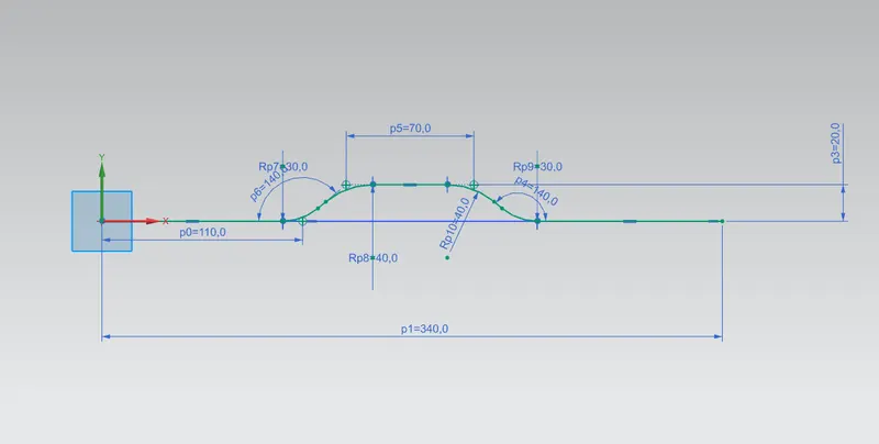
Then using contour flange command extrude the sketch upto 200 mm. Draw a rectangle on xy plane and apply normal cutout to remove a portion from contour flange. Apply break corner to all the sharp edges. Unbend the part to create bead feature. Draw a horizontal line of 200 mm length and apply bead feature to it. By using simple hole feature create holes and finally rebend to its original shape. Drafting was done at drawing work bench.
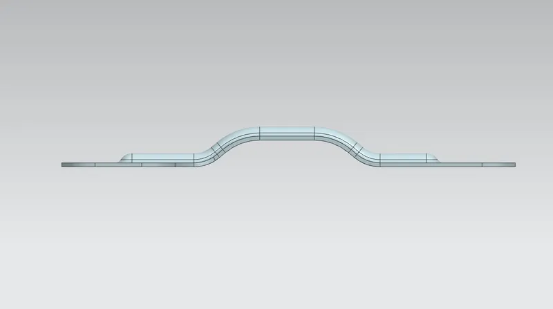
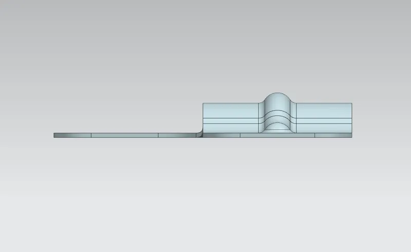
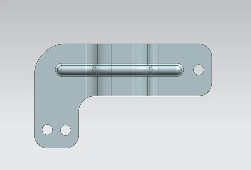
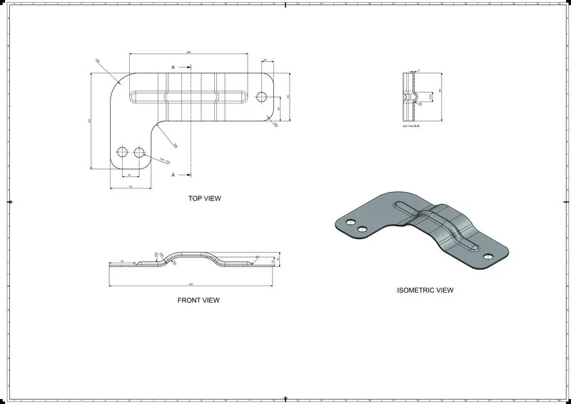
Different views of the bracket are as follows.
1. Front view:
2. Right side view:
3. Top view:
4. Isometric view:
Drawing of bracket is shown in the figure.
Feature Tree:
Conclusion:
Sheet metal bracket is designed and drafted by using NX CAD.