Advanced Sheet Metal Design Using NX Cad Challenge_6_Bracket
SHEET METAL BRACKET DESIGN USING NX CAD
OBJECTIVE:
The aim of this project to design a sheet metal bracket with some advance features using NX CAD sheet metal application.
DESIGN METHODOLGY:
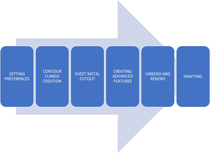
DESCRIPTION:
1. Setting preferences
The first step in sheet metal modeling is to validate the sheet metal mpreferences and modifying the global values as per the project requirement.
Creating contour flange
1. The Next step is to create a contour flange.
2. A New sketch is created in 2D plane and the this curve is used to create a flange with desired length.
Sheet Metal cutout
1. The Next phase is to cut part of the sheet metal to desired shape. Normal cutout is used which cuts the sheet metal model through projection of sketch on to the model and cutting prependicular to the faces.
2. After a 2D sketch is created it is then used to cut out the sheet metal part.
Creating advanced features
1. The Next phse is to break the sharp corners to allow easy faciltaion of tool path.
2. The sharp corners are applied with break corners which blends the model to its given radius.
3. Then the sheet metal model is prepared for adding beads and holes.
Unbend and Rebend
1. Then the sheet metal model is unbend using a statinoary faces
2. The main reason to add beads after unbend option is to have smooth projection bead surface accross the bending faces.
3. A 2D sketch is created for bead profile and it is used to lift the material that simulates the stamping tool.
4. A circular Bead is desired for this model and the depth, radius and end condition are defined.
5. The Next step is to Add a simple hole by speccfying the points at three positions.
6. Then the model is expoted to Drawing
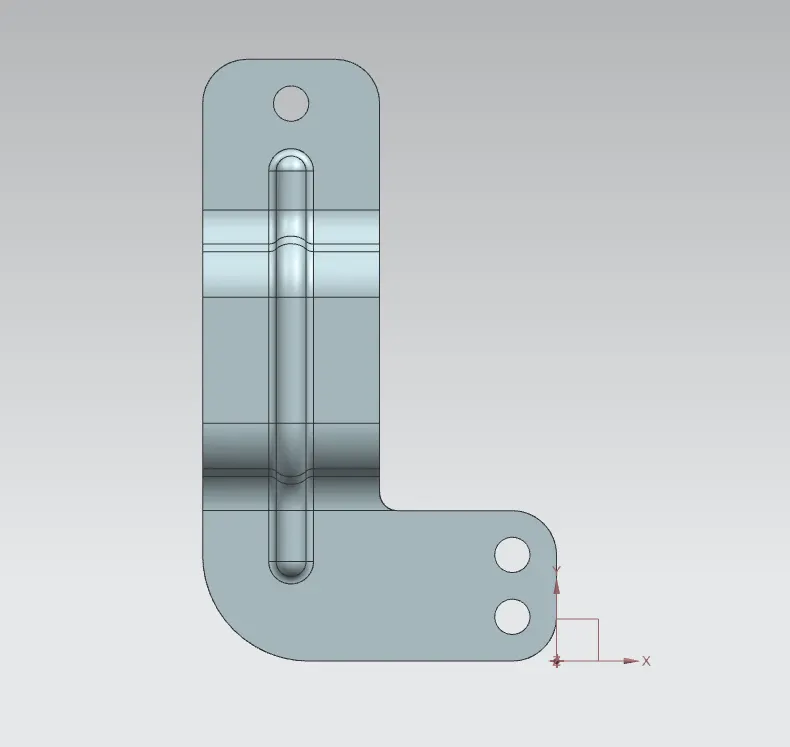
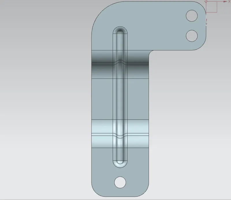
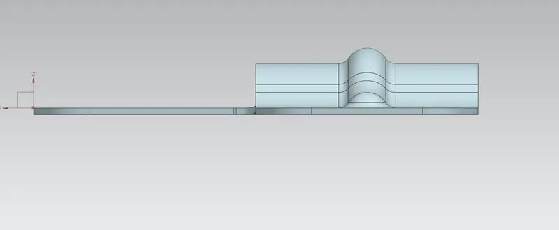
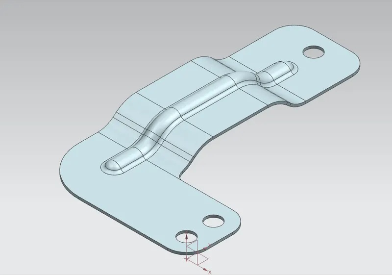
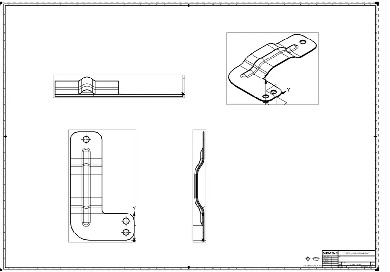
Various Model views of the created sheet metal bracket is shown below
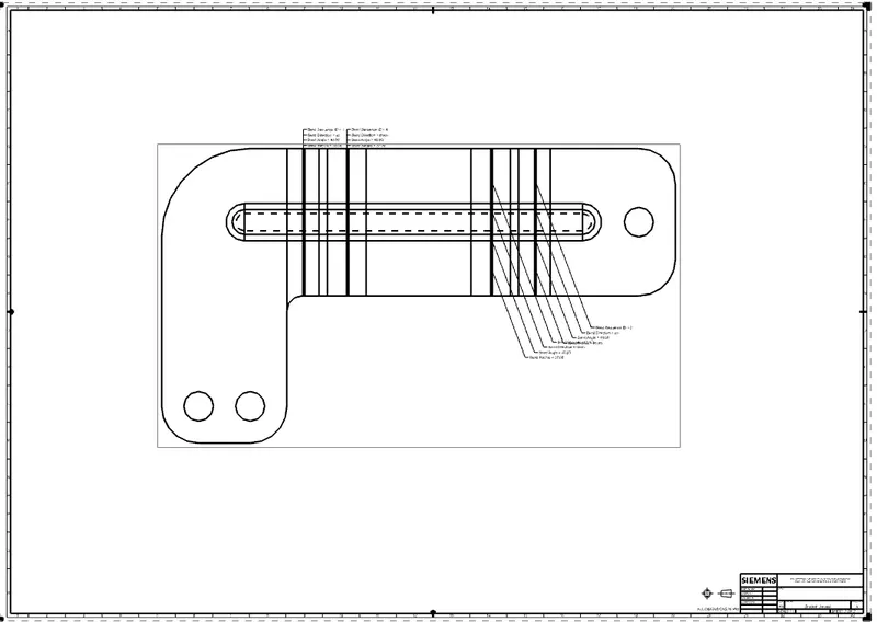
DRAWING SHEET:
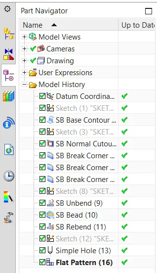
Feature tree:
CONCLUSION:
Thus the bracket design was successfully done by using NX CAD application.