Advanced Sheet Metal Design Using NX Cad Challenge_6_Bracket
AIM- Advanced Sheet Metal Design Using NX Cad Challenge_6_Bracket
Objective - design a metal sheet bracket in Siemens NX-12 and learn about the tools and features from NX
INTRODUCTION: In this project, we will see a step by step procedure of creating a bracket in Siemens NX-12. All the features used during the creation are briefly explained. We will learn about them and see how to use them too.
Design methodology
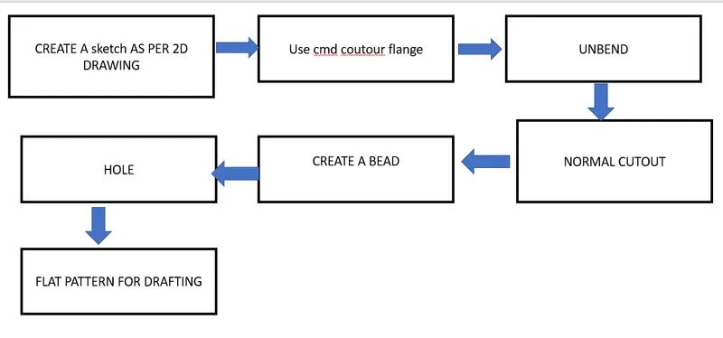
DESCRIPTION: The features used step by step during the procedure of designing are as under:
• Base Contour Flange: This is used to create a base sheet from a contour of sketch or simply extrudes an edge of a sketch along a
vector.
NORMAL CUT : Use the Normal Cutout command to cut material by projecting a sketch onto the model and then cutting perpendicular to the faces intersected .cut out of sketch.
Break Corner: This is used to convert sharp edges of model into round faces/fillet for given radius.
Unbend: It flattens the bend of a work along with the adjacent faces and gives a planar face.
• Bead: This feature is used to raise material along the contour of sketch that simulates the stamping tool
• Rebend: It recovers flatenned bends along with adjacent faces to its earlier position, along with the features added to it after unbending.
• Hole: This is used to add holes of specific diameter into a work model.
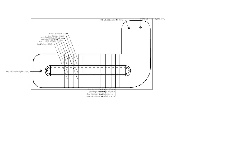
• Flat Pattern: This is used to create a flat pattern of the final model with all the necessary design parameters.
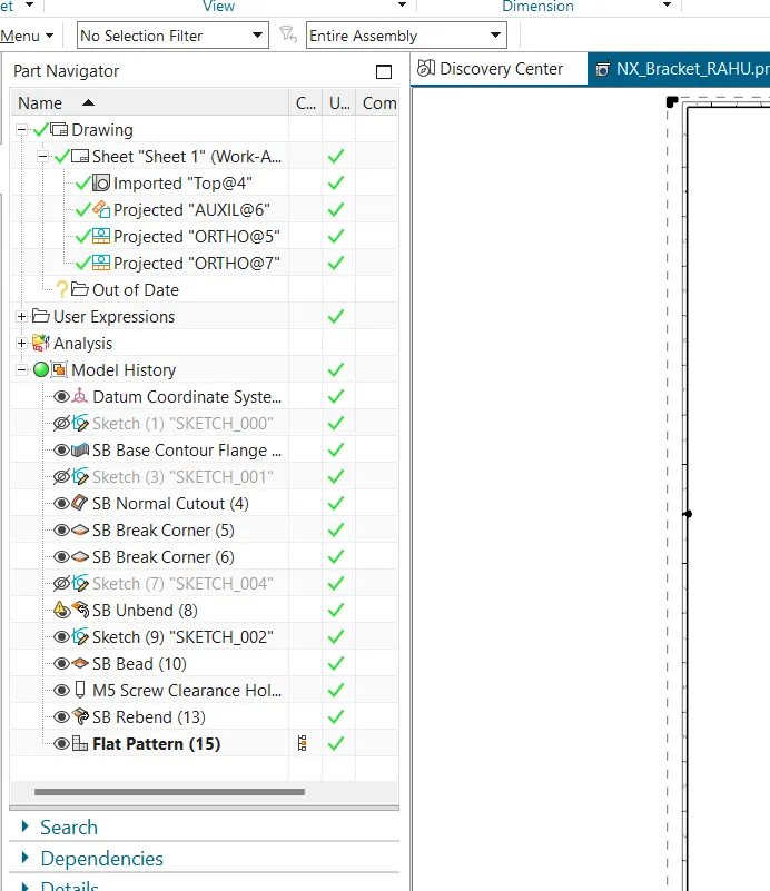
FEATURE TREE
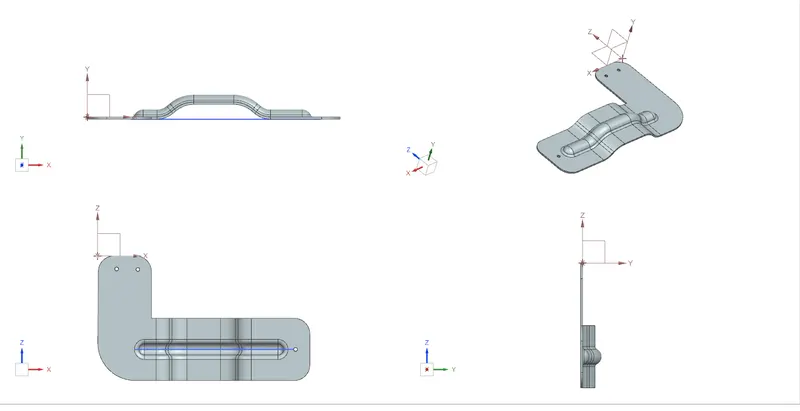
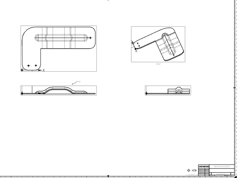
Conclusion-BRACKET CREATE ADVANCE SHEET METAL USING CMD COUNTOYR FLANGE , BEAD ,HOLE.