Advanced Sheet Metal Design Using NX Cad Challenge_5_Odd Shaped Enclosure
Sheet Metal part for odd shapes using NXCAD
Objective - To create Sheet Metal part for odd shapes using a solid body creation,and adding a flat pattern for the model which is essential for drafting.
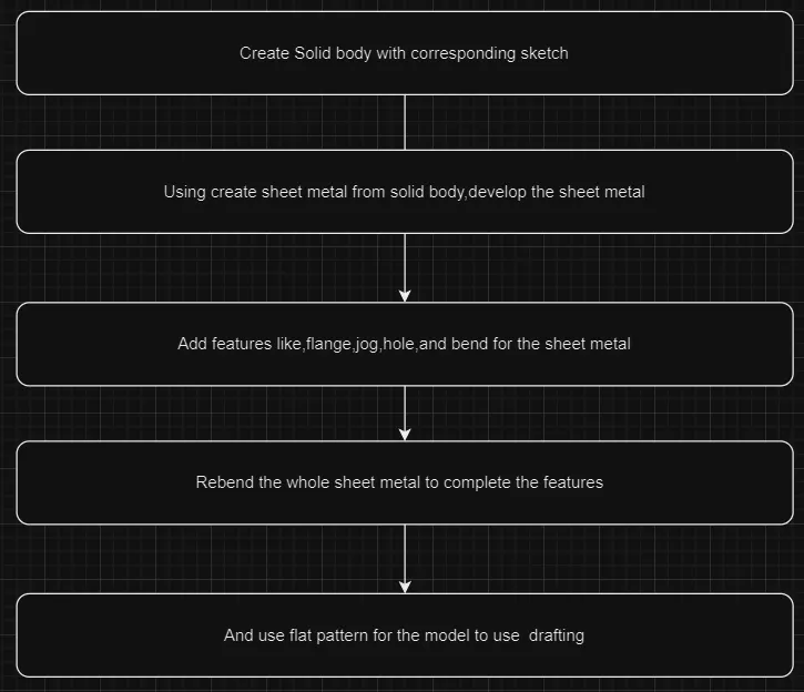
To create a sheet metal part in NX CAD, the process begins by developing a solid body that captures the interior volume of the intended component. This is achieved by sketching the desired profile and using solid modeling techniques such as extrusion. Once the solid body is created, the "Wrap Solid Body" command is used to convert the solid into a sheet metal part. From this base, various features are added to define the shape and functionality of the part. Flanges are extended from the edges to provide additional surface area or structural support, while jogs introduce offsets or steps in the metal, often used to accommodate assembly requirements or enhance rigidity. Bends are then applied to shape the part according to the design specifications, with careful attention to the radius and angle of each bend.
At this stage, specific areas of the sheet metal may need to be unbent using the "Unbend" command. This allows the part to be flattened, making it easier to add features such as holes, beads, or other details that are necessary for the part's function or assembly. Holes can be precisely placed for fasteners or other purposes, while beads are added to reinforce the metal, providing increased strength without adding weight. After these features are incorporated, the "Rebend" command is used to return the previously flattened areas to their original bent state, restoring the part to its intended 3D form.
With the part fully defined and all features added, the next step is to create a flat pattern using the "Flat Pattern" tool. This generates a 2D representation of the sheet metal part in its unbent state, which is essential for the manufacturing process, as it provides the necessary layout for cutting and forming the part from a flat sheet. The final step involves drafting, where detailed drawings are created from the flat pattern, complete with dimensions, annotations, and any other information required for production. These drawings ensure that the part can be accurately manufactured to meet all design specifications.
Conclusion: Through this process, a solid model is transformed into a detailed sheet metal part that is fully prepared for manufacturing. By carefully managing the steps of unbending, feature addition, and rebending, the design is optimized for both virtual validation and physical production. The creation of a flat pattern and corresponding detailed drawings is the final step that bridges the gap between design and manufacturing, ensuring that the part can be produced efficiently and to exact specifications.
Drawings are uploaded as a file zip.
(Its not uploading due to bigger size)