Advanced Sheet Metal Design Using NX Cad Challenge_5_Odd Shaped Enclosure
OBJECTIVE: - To design an odd shaped enclosure and create a draft of it using Siemens NX Sheet metal application.
DESIGN METHODOLOGY
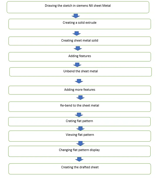
SKETCH TOOLS: Sketching is the process of creating a 2D drawing before developing it in 3D. In Siemens NX Sheet Metal, there are plenty of options and has various tools for creating a 2D sketch. In that, a few tools which are used for drawing the casing are discussed below.
STRAIGHT-LINE: The straight line is one of the sketch tools which is used to draw a straight line. It creates lines with constraint inferencing.
RECTANGLE: Creates a rectangle using any of three different methods.
POINT: It is used to create sketch points in a 2D plane.
TAB: It is used to create a base feature by extruding a sketch along a vector by a thickness value or adds material to a planar face. Additional planar selections can be added to generate bends as part of the base feature.
FLANGE: It is used to add a flat flange at an angle to a planar face and adds a bend between the two.
BEND: It is used to modify a model by bending material on one side of a sketch line, adding a bend between the two sides.
BREAK CORNER: It is used to create rounds or chamfers around sharp corners of a tab or flange
DIMPLE: It is used to lift an area of the model inside a sketch that simulates a stamping tool.
BEADS: It is used to lift the material along the contour of a sketch that simulates a stamping tool.
HEM FLANGE: This is used to modify by folding the edge of a sheet metal flange over onto itself for the purpose of safe handling or to increase edge stiffness.
NORMAL CUTOUT: It is used to create cut material by projecting a sketch onto the model and then cutting perpendicular to the faces intersected by the projection.
UNBEND: It is used to flatten a bend and the material adjacent to the bend.
REBEND: It is used to restore an unbend feature to its previous bend state, along with any features added after the unbend feature.
JOGS: This is used to modify the model by lifting material on one side of a sketch line, adding a flange between the two sides.
HOLES: It is used to add a hole to one or more solid bodies in a part or assembly with options for counterbored, countersunk, and threaded.
LOUVERS: It is used to pierce a model with a sketch line that simulates a stamping tool.
PROCEDURE:
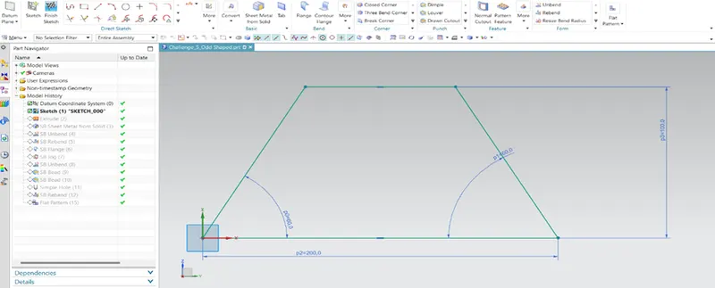
Creating the solid body:
Extrusion of the sketch: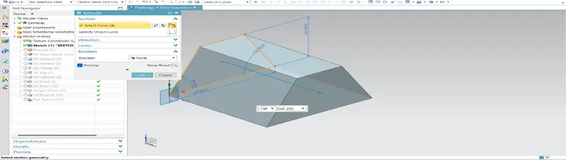
Wrap the solid body: 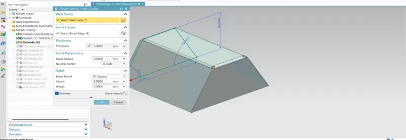 Adding Feature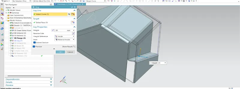
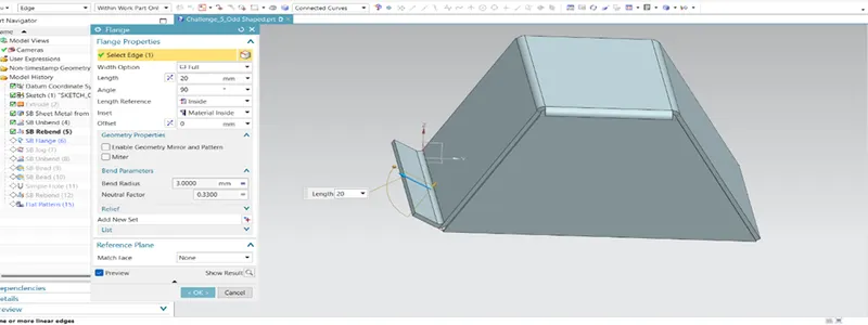
Unbend: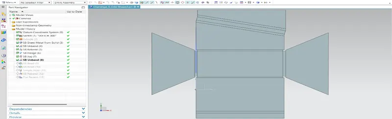
Creating Bead: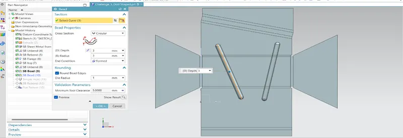
Hole creation: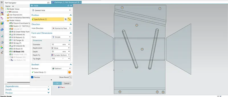
.
Flat pattern: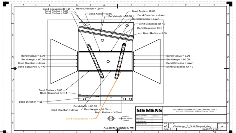
VIEWS:
FRONT VIEW:
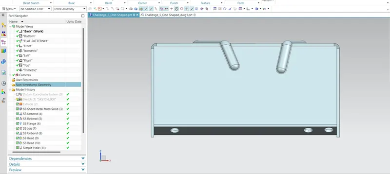
TOPVIEW:
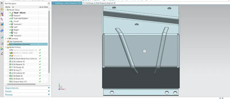
SIDE VIEW:
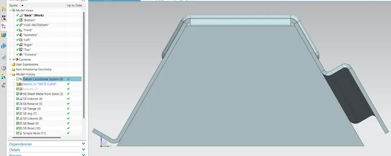
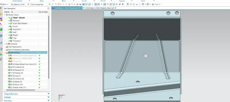
BOOTOM VIEW:
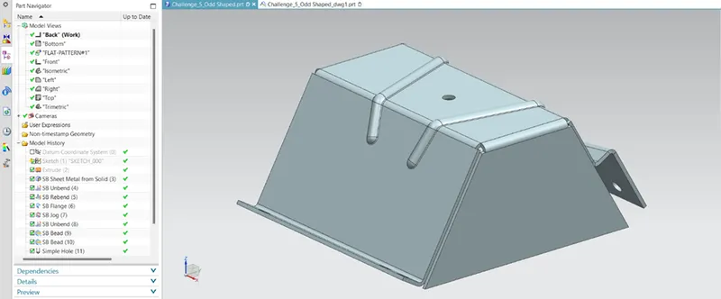
ISOMERTIC VIEW:
CONCLUSION:
Thus, the Odd Shaped Enclosure had been designed using Siemens NX Sheet Metal and various features had been executed successfully. A Drafted image of the flat pattern is also obtained.