Advanced Sheet Metal Design Using NX Cad Challenge_5_Odd Shaped Enclosure
ODD SHAPED ENCLOSURE
Objective:
To Get the clear idea of odd shaped designs in the NX CAD
Introduction:
Closures are used to protect the machine components. In the realm of electrical design, sheet metal steel enclosures are commonly utilised. They may be found in everything from junction boxes to industrial machinery control panels. Cutting processes are those in which a piece of sheet metal is separated by applying a great enough force to caused the material to fail. The most common cutting processes are performed by applying a shearing force, and are therefore sometimes referred to as shearing processes. When a great enough shearing force is applied, the shear stress in the material will exceed the ultimate shear strength and the material will fail and separate at the cut location. This shearing force is applied by two tools, one above and one below the sheet. Whether these tools are a punch and die or upper and lower blades, the tool above the sheet delivers a quick downward blow to the sheet metal that rests over the lower tool. A small clearance is present between the edges of the upper and lower tools, which facilitates the fracture of the material. The size of this clearance is typically 2-10% of the material thickness and depends upon several factors, such as the specific shearing process, material, and sheet thickness.
Design Approach:
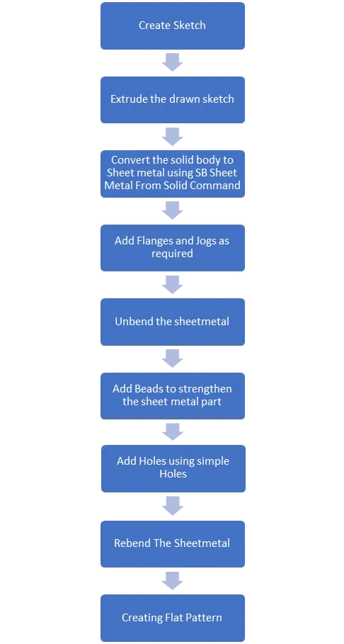
Sketching:
Sketching is a basic 2D drawing tool which is used to make the primary face of the model from which the various 3 D commands are been done.
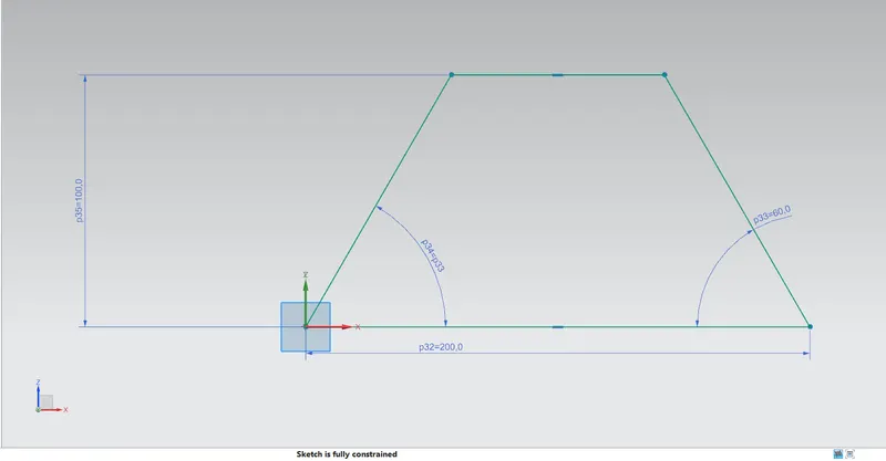
Extrude:
Extrude is the command which Makes Closed Curves into Solid body Along the vector.
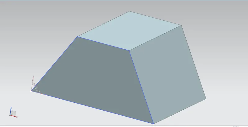
Sheet Metal from Solid:
This Converts the solid Body into the sheet metal Body with the thickness and after shearing process.
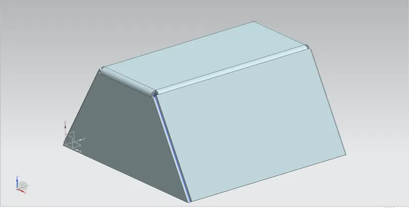
Flange:
Flange feature consists of a face and bend connected to an existing face along a straight edge. This is feature can be created using the Flange command.
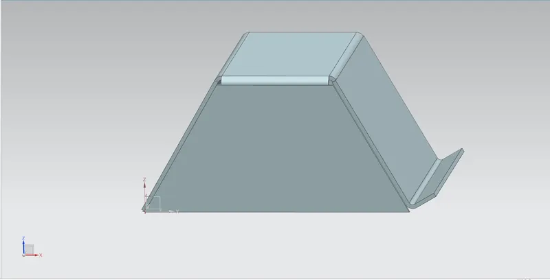
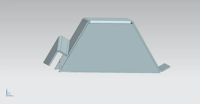
Jogs:
Modifies the Material by lifting the sheet metal along the sketch line and creates the flange on the two sides on the material.
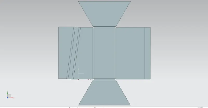
Unbend:
Unbend the sheetmetal shearing using the unbend.
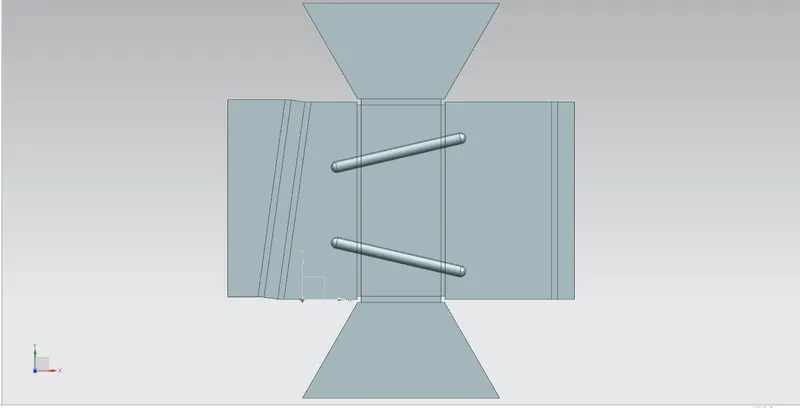
Beads:
Lifts the material along the contour Sketch which used to strength the material.
Holes:
Holes are creating using this command at the particular point.
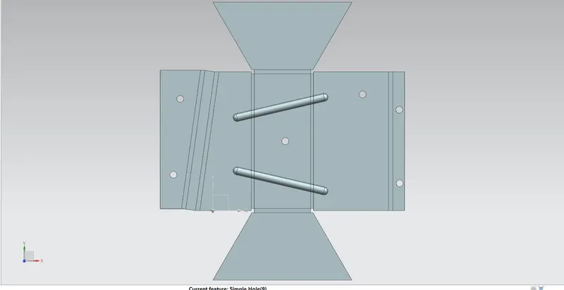
Rebend:
Rebend is the process bending the sheetmetal.
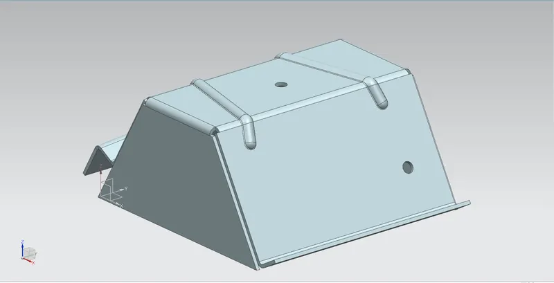
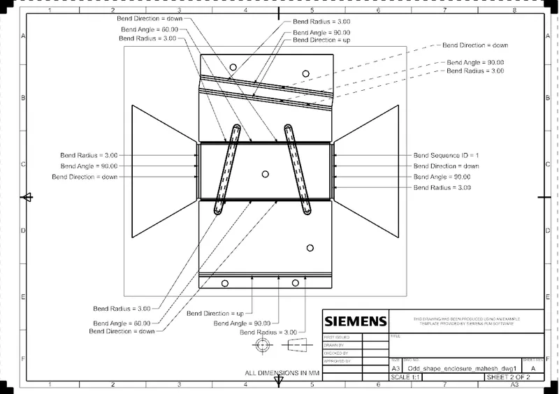
Flat Pattern:
Flatpattern gives the unbend the sheetmetal.
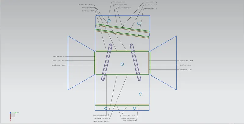
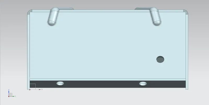
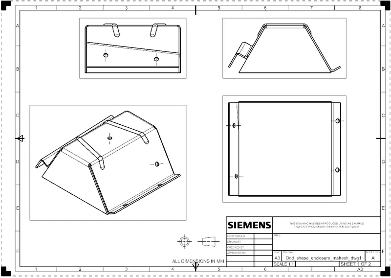
FRONT VIEW:
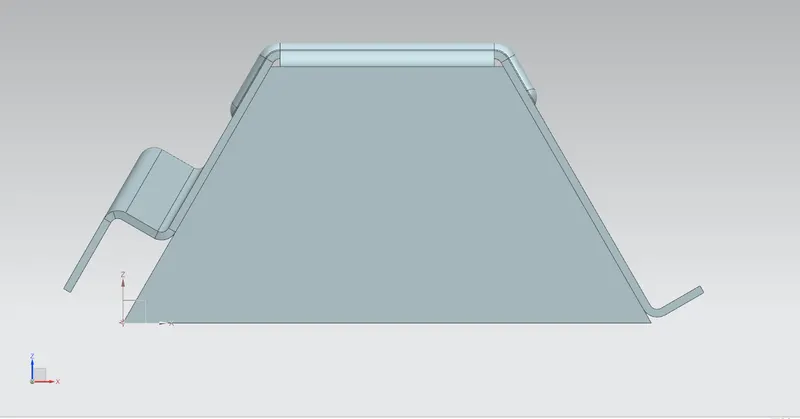
RIGHT SIDE VIEW:
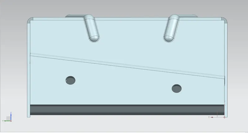
LEFT SIDE VIEW:
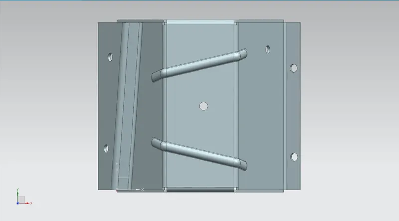
TOP VIEW:
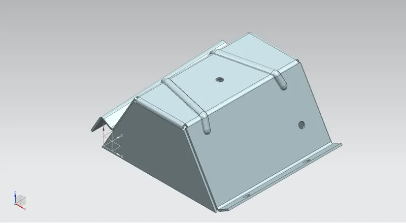
ISOMETRIC VIEW:
DRAWING SHEET:
CONCLUSION:
Got the clear idea of complex sheet metal enclosures.
- Part Files attached
- Zip file attached
- Drive