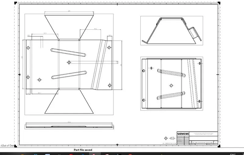
Advanced Sheet Metal Design Using NX Cad Challenge_5_Odd Shaped Enclosure
Write a detailed report on Sheet Metal Component with good explanation on Sheet Metal modelling tools applied throughout the modelling. Also attach the Final model Images (Min. 4 images) of Sheet Metal Odd Shaped Enclosure.
Advanced Sheet Metal Design Using NX Cad Challenge_5_Odd Shaped Enclosure
OBJECTIVE:-
To design a sheet metal odd-shaped enclosure using NX Cad software with suitable commands to achieve the final product as per the inputs.
INTRODUCTION :
Sheet Metal is a type of material that is flattened into thin sheets. Sheet metal is made by taking a large cast in and rolling it into a long ribbon of the thickness it wants. This flat metal is rolled into a coil and sent directly or cut the metal into sheets before being sent to a machine shop.
The sheets are made from metals such as aluminum, brass, copper, steel, tin, nickel, and titanium. The sheet’s thickness depends on the material needed for a project. Thicknesses can vary from 0.15 -6.00 mm significantly; extremely thin sheets are considered foil or leaf, and pieces thicker than 6 mm (0.25 in) are considered plate steel or “structural steel.”
DESIGN METHODOLOGY
The design methodology is explained by the flow chart as follows :
START NX WITH SHEET METAL

SKETCH HAS MODE & EXTRUDE
SHEET METAL FROM SOLID IS PERFORMED
FLANGE IS CREATED & JOGS IS CREATED ON THE OTHER SIDE
UNBEND IS PERFORMED FOR THE MODEL
BEAD IS CREATED ON THE SURFACE
HOLE IS PERFORMED AS PER THE DESIGN
FLATE PATTERN IS SHOWN AT THE END
Description
- nx has been opened and selected sheet metal design with unique name
- creating sketch is xy axis from given data
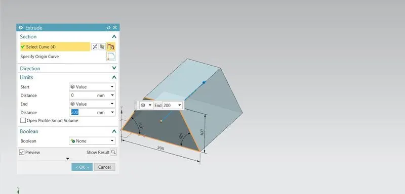
- sketch as reference extrude has been down
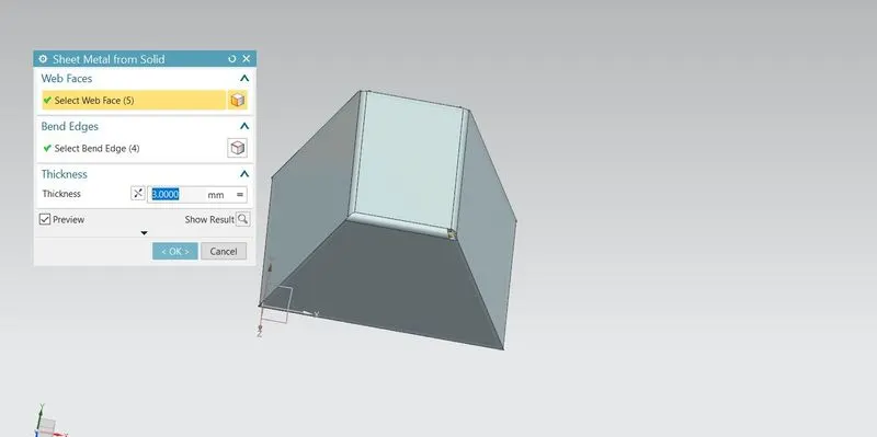
- converting this solid model into sheet metal
- sheet metal is formed thickness of 3 mm and bend radius of 3mm
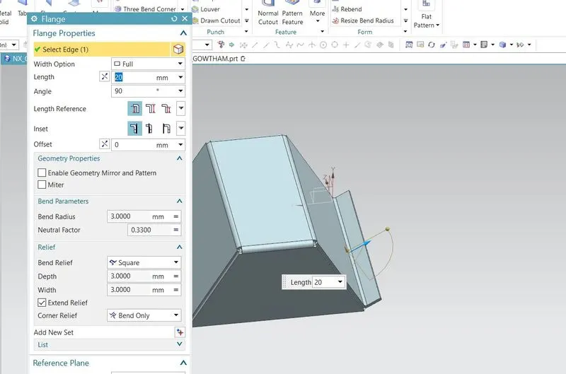
- then flange is created on one edge for 20mm
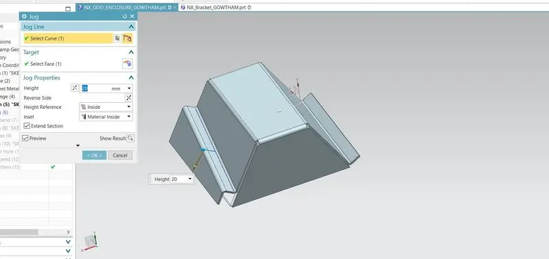
- sketch has created to form jog comand
- with the reference of sketch, jog has been performed
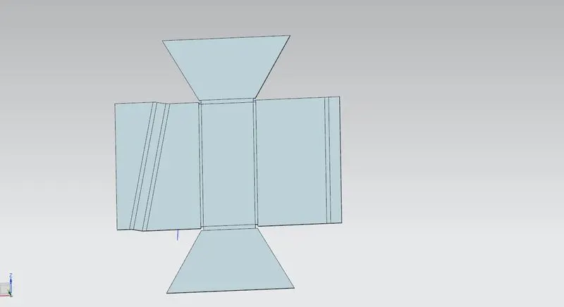
- unbend is down for this model to check model con be happen or not
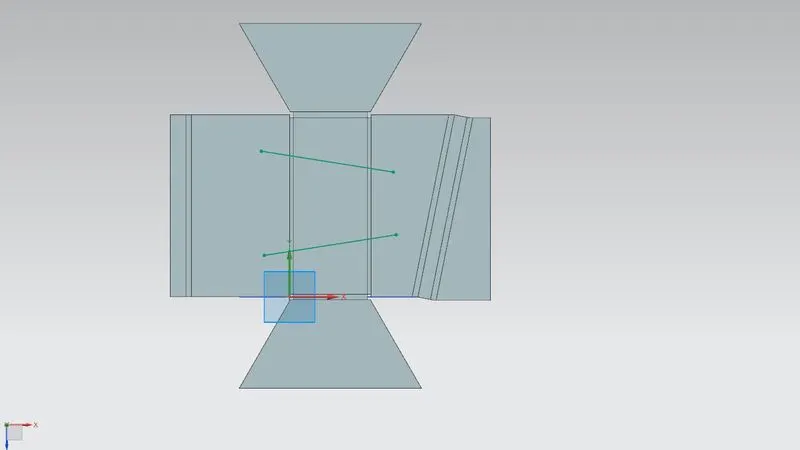
- now again the sketch takes the role on the top of the unbend surface
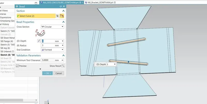
- with the help of sketch bead is performed to give max strength to the model
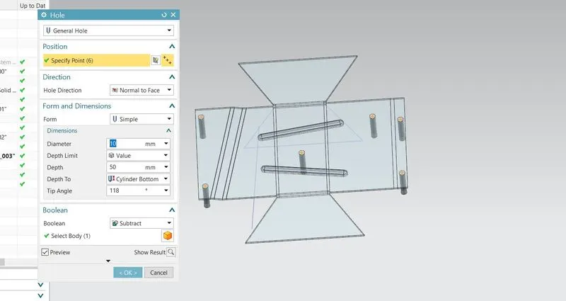
- as per the design, consideration hole is maded
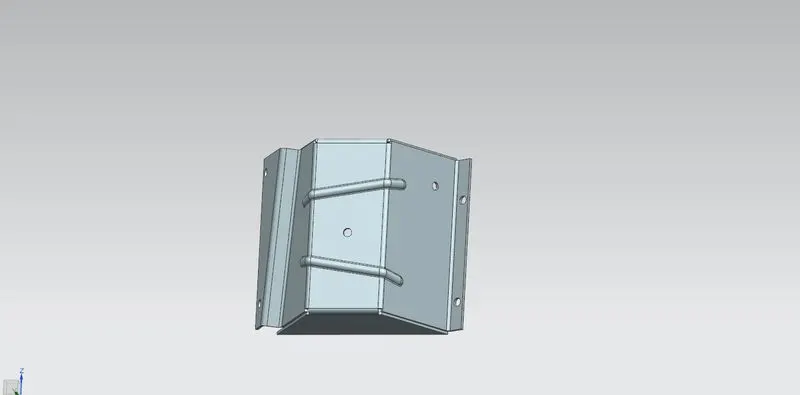
- finally rebend is used to see the final out put
Creating the solid body
The sketch for the solid body has to be created. Then the sketch is to be extruded using Extrude command which is available in the modelling workbench.
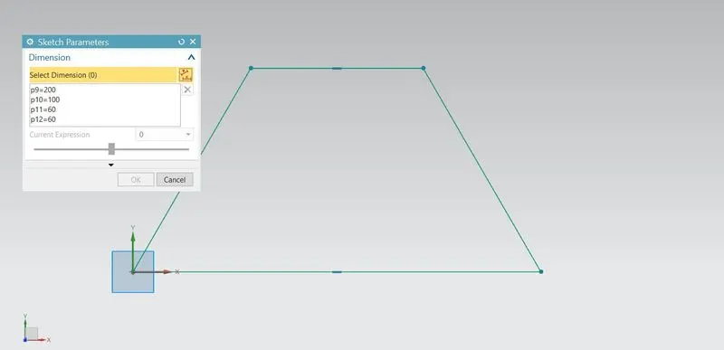
EXTRUDE
The sketch is extruded upto 200mm. Thus the solid body is ready to wrap up with the sheet metal over the surface.
SHEET METAL FROM SOLID
sheet metal is formed from solid in the thickness of 3 mm and radius of 3mm
FLANGE
the flange is created on one side with an angle of 20 mm and an angle of 90
JOG
JOG is created with the reference of the sketch with a length of 20 mm
UNBEND
unbend performed and shown bellow
SKETCH HAS BEEN FORMED AT TOP
BEAD HAS BEEN CREATED AT THE TOP WITH THE REFERENCE OF THE SKETCH
THE HOLE IS CREATED PER DESIGN AND DISPLAYED BELOW
REDEND TO ORGINAL SHAPE
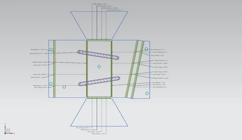
FINALLY FLATE PATTOM IS SHOWN BELLOW
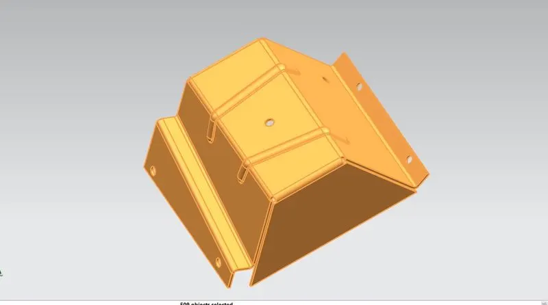
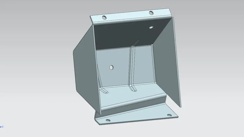
SAMPLE IMAGE
2D DRAWING