Designing of Sheet Metal Odd Shaped Enclosure - Using NX CAD
DESIGNING OF SHEET METAL ODD SHAPED ENCLOSURE - USING “SIEMENS NX CAD”
Objective:
The main objective of this project is to design a sheet metal odd shaped enclosure using the - “Siemens NX CAD” software.
Introduction:
Sheet metal:
Sheet metal is metal formed into thin, flat pieces, usually by an industrial process. Sheet metal is one of the fundamental forms used in metal working, and it can be cut and bent into a variety of shapes.
Thickness can vary significantly; extremely thin sheets are considered foil or leaf, and pieces thicker than 6mm (0.25 inch) are considered plate, such as plate steel, a class of structural steel.
Sheet metal is available in flat pieces or coiled strips. The coils are formed by running a continuous sheet of metal through a roll slitter.
There are many different metals that can be made into sheet metal, such as aluminium, brass, copper, steel, tin, nickel and titanium.
Sheet metal is used in automobile and truck (lorry) bodies, major appliances, airplane fuselages and wings, tinplate for tin cans, roofing for buildings and many other applications.
Odd shaped enclosure:
Odd shaped enclosure is the enclosure with odd shapes or angles. These enclosures are created by taking the shape of a solid body, by wrapping the sheet metal over it.
Design Approach:
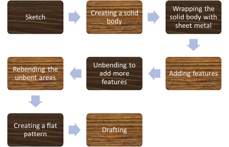
Description:
The following tools and features of siemens NX CAD are used in the casing design,
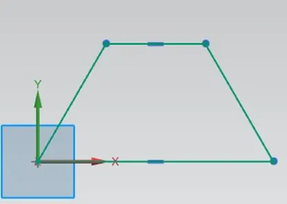
Sketch:
This feature is used to create 2D drawings along the required planes and faces.
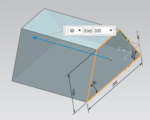
Extrude:
Use the extrude command to create a solid or sheet body by selecting a section of curves, edges, faces, sketches or curve features and extending them in a linear distance. The following example shows how extrude can form a solid body from a section of curves.
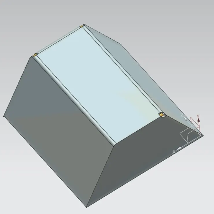
Sheet metal from solid:
This command builds a sheet metal model that takes its shape from a collection of planar faces of a solid. The sheet metal model forms over the solid and avoids sharp corners.
Flange:
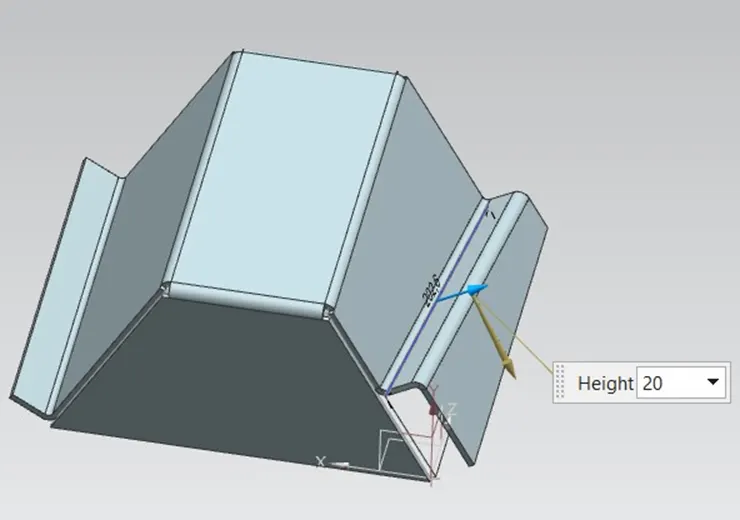
This command is used to add a flat flange at an angle to a planar face and add a bend between the two edges or walls. The flange can only be made on a straight edge.
Jog:
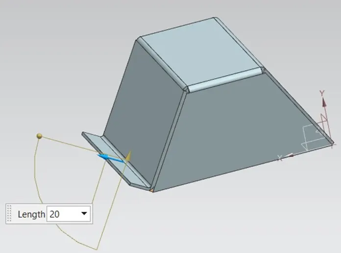
Use the jog command to create an offset or a step in a tab. You can use small jogs to provide clearance or rigidity to a part. The section for the jog must consist of a single line across a planar face. NX creates the jog by lifting material on one side of the jog line and adding a flange between the two sides.
Unbend:
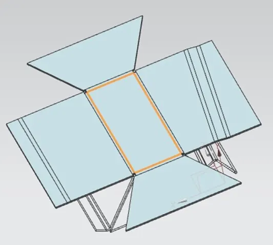
Unbend command is used to flatten the model through selected bends with respect to selected face. All the flanges and bends of a model are flattened using this command to add more features.
Bead:
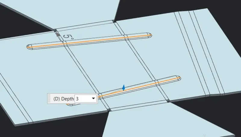
Bead tool is used to create an embossed or engraved bead on sheet metal part using single entity or a set tangentially connected entities.
Hole:
Hole command constructs one or more holes in the ordered environment. We can use the hole command to construct simple, threaded, tapered, counterbored, and countersunk holes.
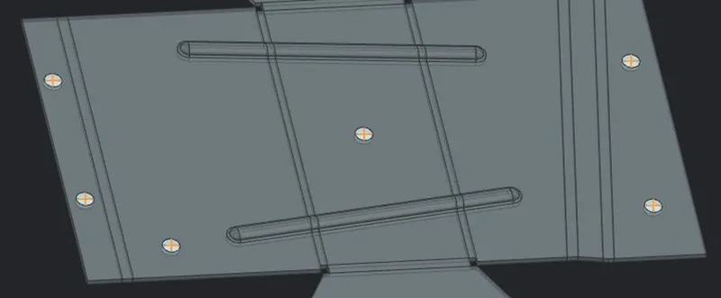
Rebend:
Rebend command helps us to restore an unbend feature to its previous bent state, along with any features added after the unbend feature.
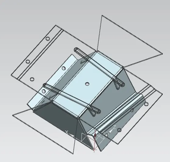
Flat pattern:
Flat pattern feature is used to create another part view where the model becomes flat from the formed sheet metal part with all the details.
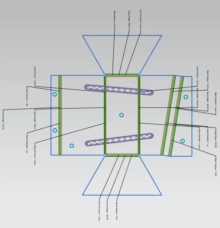
Drafting:
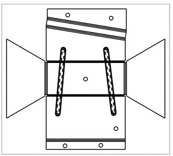
Drafting, also spelled draughting, also called as engineering drawing, graphical representation of structures, machines, and their component parts that communicates the engineering intent of a technical design to the craftsman or worker who makes the product.
For this project, a new drafting file is created in A3 size and a new base view is added with the flat pattern created before in 1:2 scale ratio.
Standard views of Odd shaped enclosure:
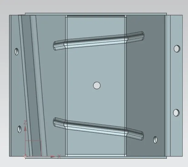
Front view.
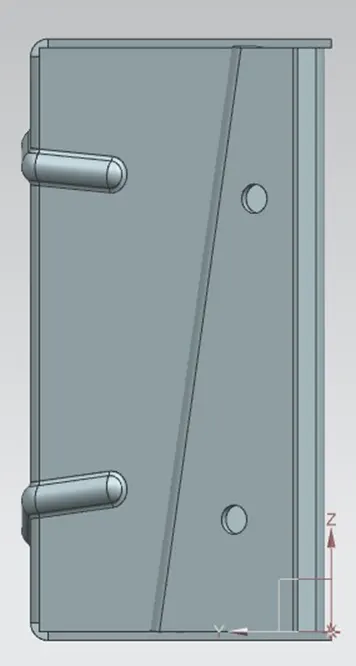
Side view.
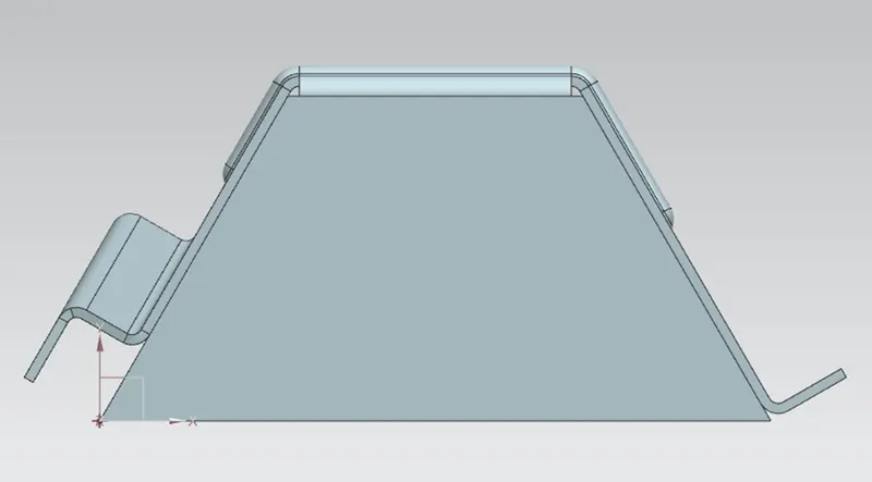
Top view.
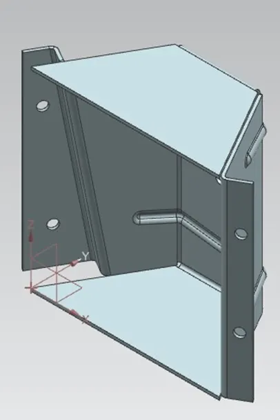
Isometric view.
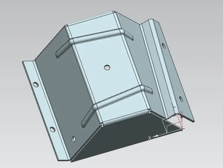
Custom view.
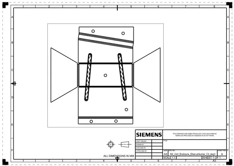
Odd shaped enclosure draft sheet.
Conclusion:
The sheet metal odd shaped enclosure is designed with the help of tools and features in “Siemens NX CAD” software.