Advanced Sheet Metal Design Using NX Cad Challenge_5_Odd Shaped Enclosure
ODD SHAPED ENCLOSURE
OBJECTIVE
Here we need to design an odd shaped body & convert that body into a sheet metal.Also we need to prepare the Flattern body for the designed odd shaped body.
INTRODUCTION
- Sheet Metal Fabrication is the process of forming parts from a metal sheet by punching, cutting, stamping, and bending.
- 3D CAD files are converted into machine code, which controls a machine to precisely cut and form the sheets into the final part.
- Sheet metal parts are known for their durability, which makes them great for end use applications (e.g. chassis). Parts used for low volume prototypes, and high volume production runs are most cost-effective due to large initial setup and material costs.
- Because parts are formed from a single sheet of metal, designs must maintain a uniform thickness. Be sure to follow the design requirements and tolerances to ensure parts fall closer to design intent and cutting sheets of metal.
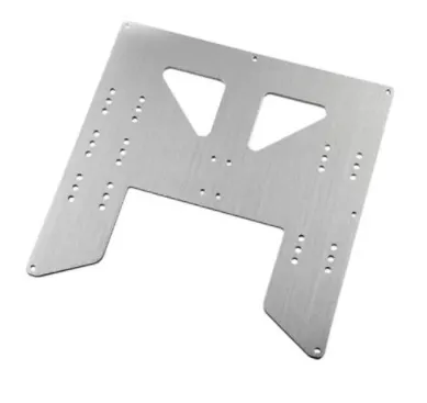
Bending
- Bending is a process whereby a force is applied to sheet metal which causes it to bend at an angle and form the desired shape. Bends can be short or long depending on what the design requires.
- Bending is performed by a press brake machine that can be automatically or manually loaded. Press brakes are available in a variety of different sizes and lengths (20-200 tons) depending on the process requirements.
- The press brake contains an upper tool called the punch and lower tool called the die between which the sheet metal is placed.
- The sheet is placed between the two and held in place by the backstop. The bend angle is determined by the depth that the punch forces the sheet into the die. This depth is precisely controlled to achieve the required bend.
- Standard tooling is usually used for the punch and die. Tooling material includes, in order of increasing strength, hardwood, low carbon steel, tool steel and carbide steel.
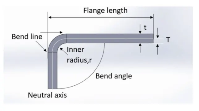
(This above fig shows the Critical Dimension that are affect while bending)
DESIGN METHODOLOGY
Flow Charts for the Design steps
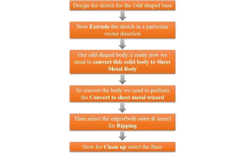
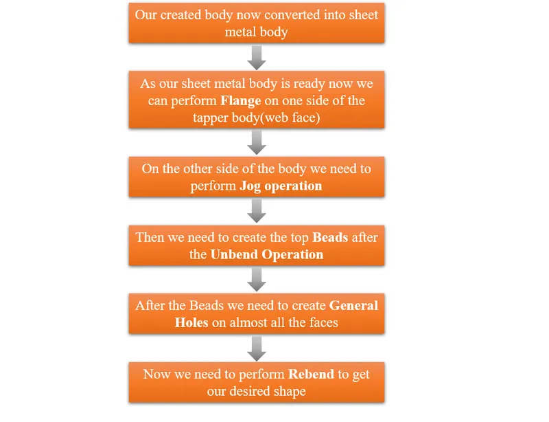
Images for Different types of View
ISOMETRIC VIEW
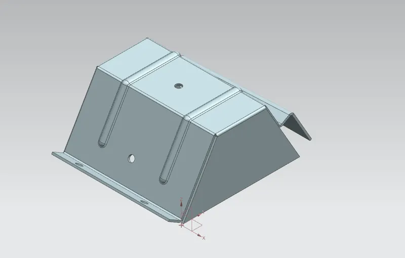
FRONT VIEW
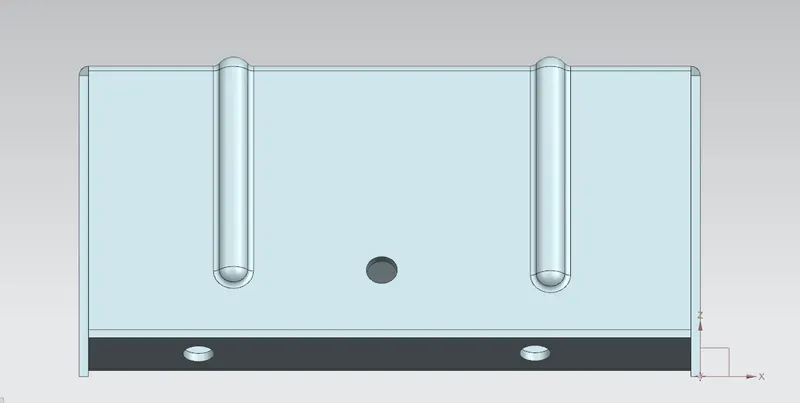
LEFT SIDE VIEW
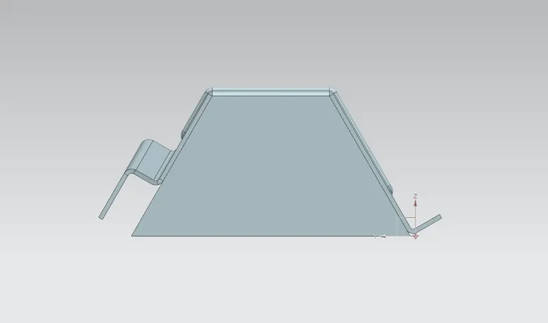
TOP VIEW
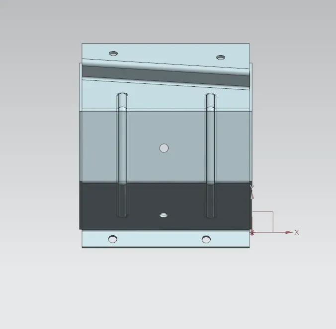
FLAT SOLID VIEW
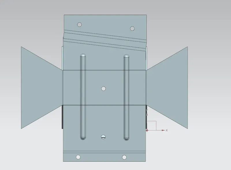
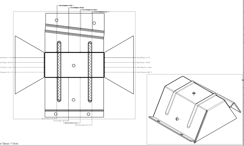
Now the 2d representation for the Flat pattern will be shown in the drawing file.
FLAT PATTERN VIEW
CONCLUSION
In this challenge we saw the operations like--Convert to Sheet metal Wizard,Jog,Flat Solid ,Beads,Holes etc.And also we saw what are the errors we arrise while performing the Convert to sheet metal Wizard,and how to solve them.