Advanced Sheet Metal Design Using NX Cad Challenge_2_Box Assembly
TITLE: Sheet Metal Box Assembly Design using Siemens NX.
OBJECTIVE: To learn the sheet metal design process and to design a sheet metal box assembly in parametric Cad software Siemens NX following industrial work flow.
INTRODUCTION: Sheet Metal is a metal with small thickness ranging from 0.5 – 6MM which is made thin flat by rolling or hammering process. A number of mechanical components are made up of Sheet Metal. Sheet metal is widely used in manufacturing industry due to its various advantages. In this project, a box assembly of sheet metal is designed in Siemens NX -CAD software following the industrial approach.
This Sheet Metal box assembly consists of the main box, cover and the hinge made out of sheet metal itself. All the parts are designed using the sheet metal features as presented here.
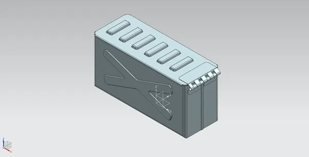
DESIGN METHODLOGY: The box assembly designed for this project consists of features like tab, flanges, cut-outs, bends, hem flanges, dimples and beads. Every feature is designed in an order following the industrial procedure to keep the design intent. The design methodology used for this project can be summarized as depicted in flow chart below.
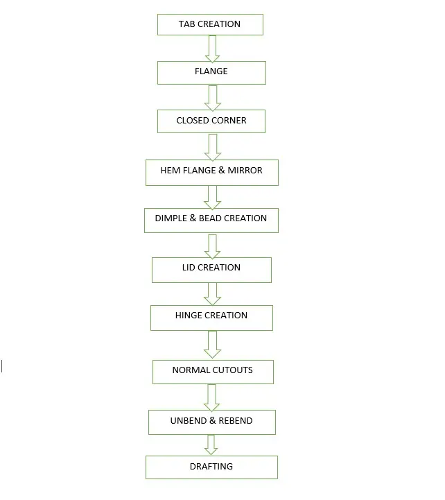
DESCRIPTION:
SKETCH: Sketch tool was used for creating the sketch required for tabs, cut outs, dimples, beads etc….
TAB: Tab is the base feature of sheet metal modelling. Tab is created by extruding a sketch along a vector by adding a thickness value.
FLANGE: A flange is external or internal ridge. Flanges were used to create the side walls of the box as well as hinges.
HEM FLANGE: This feature is used to fold the sheet metal flange back to the body itself. It was applied on the edges of box assembly for safe handling. It also improves the toughness of edges and prevent the damages that may occur to the edges of the box.
DIMPLE: Dimples are used to lift the material according to a sketch that simulates a stamping tool.
BEAD: Beads are used to enhance the strength of the sheet metal part. It lifts the material according to a sketch that simulates a stamping tool. Here, four beads were used at the bottom of the box assembly.
MIRROR BODY: It is used to mirror an existing body across a plane.
MIRROR FEATURE: It is used to mirror a feature across a plane. Here the features such as beads were mirrored using this feature.
NORMAL CUT-OUT: This tool is used to cut the material by projecting a sketch onto the model and then cutting normal to the faces intersected by the projection.
UNBEND: This feature is used to unbend the adjacent bends and flatten them.
REBEND: It is used to rebend the unbended corners after adding any features on the faces.
CLOSED CORNER: Used to close the corner where two adjacent flanges meet by extending the bends and flanges. It eliminates the gap between adjacent flanges which were used to create walls of the box assembly.
BREAK CORNER: It is used to round or chamfer the sharp corners of a tab or flange.
DATUM PLANE: Here, datum plane was used to create lid of the box. Datum plane is used to construct additional features.
UNITE: It combines the two or more bodies into a single body. It was used to combine the body which was mirrored across a plane.
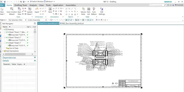
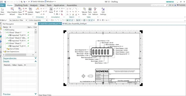
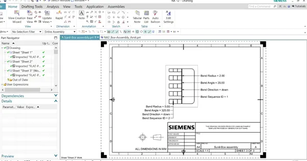
FALT PATTERN: Flat pattern is the representation of the entire sheet metal component in the 2D form of the flat sheet metal with all the bends, cut-outs, holes and additional features in the form of lines or edges. The flat pattern ensures the ability to cut the sheet metal out of the raw sheet metal plate. It removes the possible errors such as interference or collision with in the same component.
DRAFTING: After the design is complete, the execution or the manufacturing of the component requires a technical drawing of the component with the provided scale and with accuracy. The necessary details such as annotations, callouts, bend tables can be added as per the requirement.
STANDARD VIEWS: Several standard views such as front, top, side and isometric views of the box assembly are shown below.
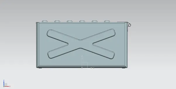
FRONT VIEW
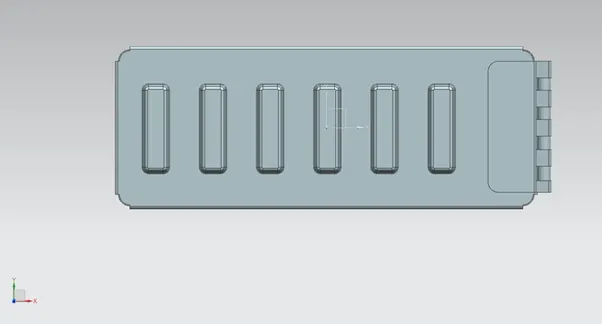
TOP VIEW
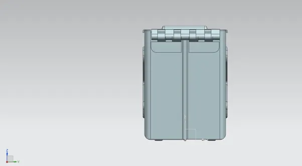
SIDE VIEW
ISO METRIC VIEW
CONCULSION: In this project, a sheet metal box assembly is successfully designed in the sheet metal work bench of Siemens NX. The advantage of parametric modelling environment is used to maintain our desired design intent and all the necessary features are applied in order following the industrial workflow.