Advanced Sheet Metal Design Using NX Cad Challenge_2_Box Assembly
DESIGN AND MODELLING OF SHEETMETAL BOX ASSEMBLY IN NX-12
OBJECTIVE
To design and model the sheet metal box assembly in nx-12 by using some basic feature and tools.
To learn to create sketches on defined planes as per requirement.
To master the user interface and basic feature of sheet metal application in nx-12 like tab ,flange, break,
corner, unbend, re bend, dimple bead, mirror body, closed corner, and hem.
INTRODUCTION
Sheet metal design and fabrication
sheet metal fabrication is the process of forming part from a metal sheet by punching , cutting ,stamping, and bending.
3d cad files are converted into machine code ,which control a machine to precisely cut and forms the sheet into final part .
Sheet metal part are known for their durability ,which makes them great for end use application .part used for low volume
Prototypes and high volume production runs are most cost- effective due to large initial setup and material coasts.
Because part are formed from a single sheet of metal ,design must maintain a uniform thickness.be sure to follow the design requirement
And tolerance to ensure parts fall closer to design intent and cutting sheets of the metals .
DESIGN METHODOLOGY/APPROACH
FLOW CHART
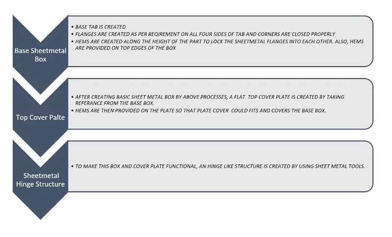
DESCRIPTION :tools/features used while desigining the box assembly create .
1Tab : tab is the basing feature in sheet metal enviroment of nx-12 the tab is the initial or the startup stage of the design
Of the sheet metal component by using the tab feature we create a base for sheet metal component and decide the thickness of the sheet metal which is the followed in the further steps of design

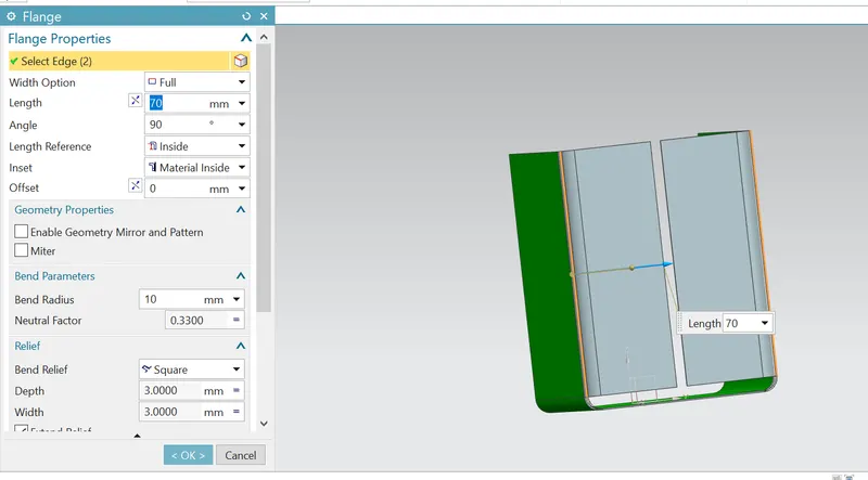
2Flange : flange feature is used to create an extended portion or bend to the selected edge. While creating flange we have to set
Different parameter such as length of the flange , its angle ,length ,reference inset other parameter like bend radius ,bend relief,
And neutral factor is also needed to be considered.
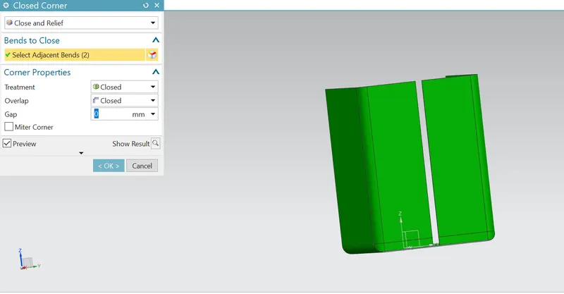
3Closed corner : this feature closes two adjacent flange corner in sheet metal application .
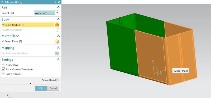
4 Mirror body : the mirror body command is used to mirror an entire body across a datum plane .for
Example ,you can use this command to form the other hand of a left hand or right -hand part .
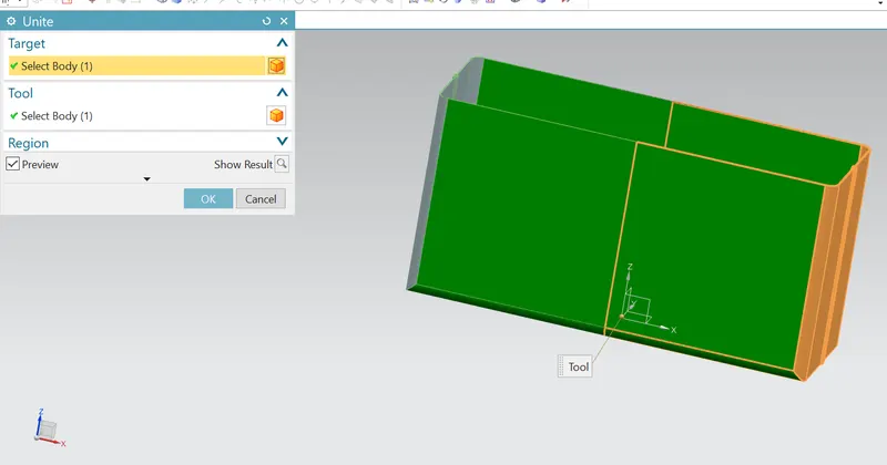
5 Unite : the unite command is used to combine the volume of two more solid tool bodies into a single
Target body .the target body and tool body must overlap or share faces so that the result is a valid solid body
This command create a unite feature.
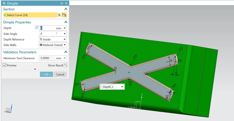
6 Dimple : this command is use to lift an area of the model inside a sketch that simulates a stamping tool.
We can create an indentation in a sheet metal part using a sketched section as the dimple outline.
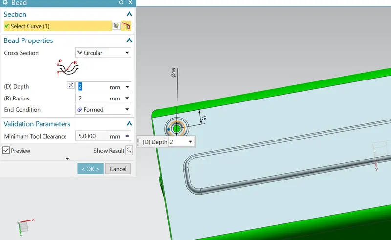
7 Bead : the bead is like a raised rib in the sheet metal panel. It requires that you have a least one sheet metal panel
In the active part as well as an open or closed -loop sketch.
The bead is another feature that has only a button for option on the command bar.
8Hem : this command is used to modify the model or folding the edge of the sheet metal flange over onto itself
For the purpose of safe handling or to increase the stiffness of the flange.
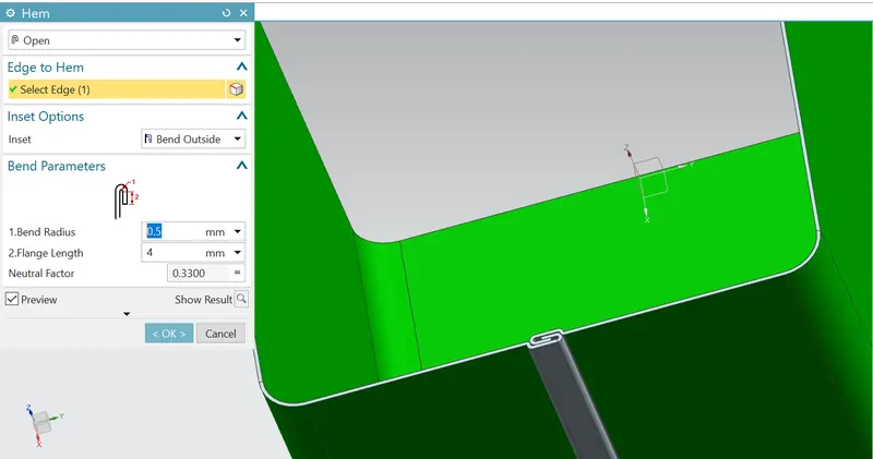
9 RE bend : re bend feature is used to get the original bend shape after performing forming operations like a dimple, bead.
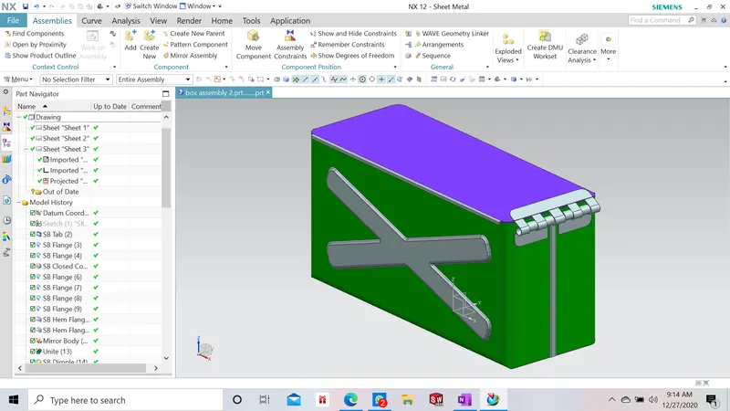
Conclusion :
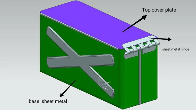
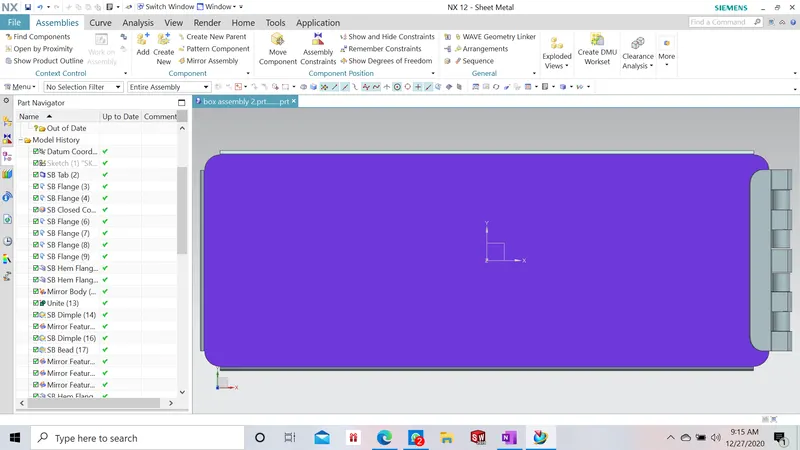
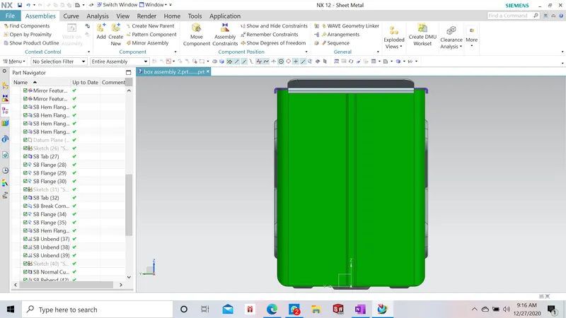
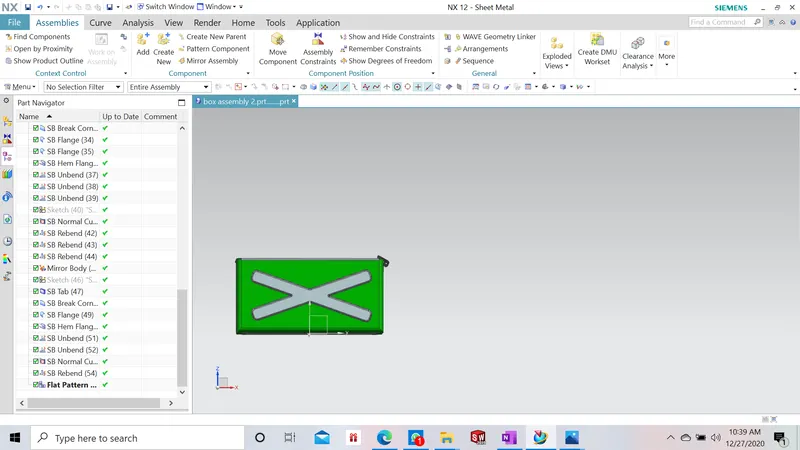
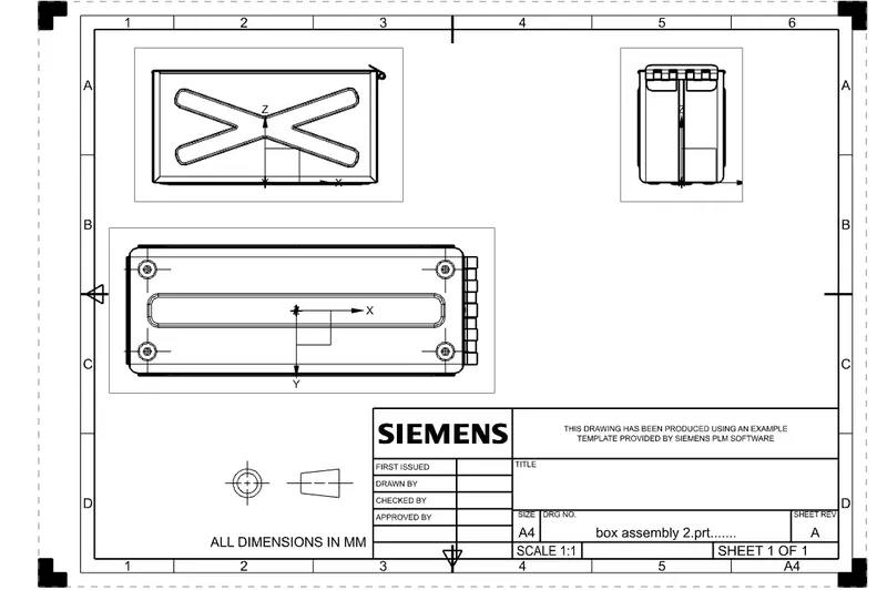
sheet metal box assembly is designed successfully in nx-12 sheet metal enviroment
some more feature in the sheet metal environment pf nx-12 like the closed corner , mirror body, unite body,
hem are learned and mastered.