Advanced Sheet Metal Design Using NX Cad Challenge_2_Box Assembly
Title: Box Assembly
Objective:
To create a Box Assembly model using Advanced Sheet Metal tools in NX-12.
Introduction:
Sheet Metal can be used as a cut and bend for the different shape of part and creation of different sheet metal part using Tab, Flange, etc.,
In this challenges I compute the Box Assembly with the help of NX-12 software.
Design Methodology:
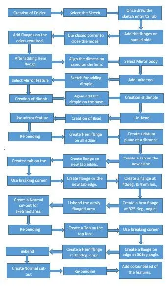
Tools Used:
Tab:
To create a sketch and adding the Tab tool for creating the base of the model. Tab tool is used to add the thickness of the sketched area(Extrude).
Normal Cut-Out:
To remove the metal from the sheet metal to use the Normal Cut-out Before create a sketch for the metal removing area.
Flange:
Create a Flange at the required places. Add the flat flange at the required place of the model.
Breaking corner:
To remove the sharp edges on the model using break corner tool. To remove all the sharp edges.
Unbend:
Using unbend tool to select the stationary face and bending face to unbend the model.
Dimple:
Dimple is used to lift an area of the metal inside for the sketched area. To add the depth of the dimple required on the dialog box.
Beads:
To create a duct shape in the model bead tool to be used. Draw the sketch on the required shape of duct, then create the bead to enter the value on the dialogue box.
Re-bending:
Select the bending areas in the reverse order of the bend. To select the stationary face and bending surface using the re-bending tool.
Flat pattern:
Select the full model to the flat pattern. It used for the drafting purpose of the model.
Hem Flange:
Modify the edges of the sheet metal parts by folding onto itself for the purpose of safe handling or increase edge stiffness. To select to folding edge to create the hem flange.
Mirror Body:
Select the body which one want to mirror based on the plane. Then select the plane to mirror the body.
Mirror Features:
Select the features which one want to mirror based on the plane. Then select the plane to mirror the features.
Unite:
Select the two or more bodies to unite in a single body
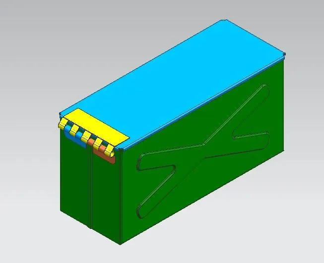
Final Output Model:
Conclusion:
In this challenge creating the Box Assembly using NX-12 is successfully completed and attached the images in the views and part model of the Box Assembly.