Advanced Sheet Metal Design Using NX Cad Challenge_2_Box Assembly
BOX ASSEMBLY
Objective:
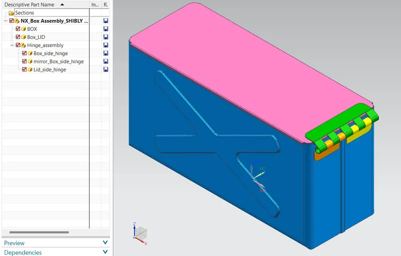
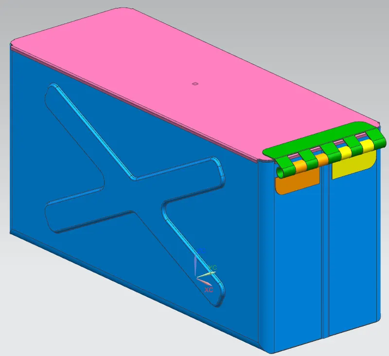
Design a box assembly with closing lid.
Design Methodology:
- Created a new assembly file named NX_Box_Assembly_Shibly
- Added new part named box and made it work part for box designing.
Box Designing:
Step:1 - Making the base and side walls.
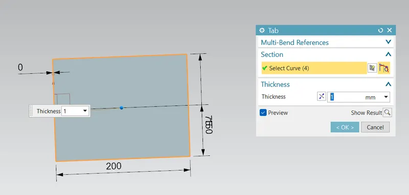
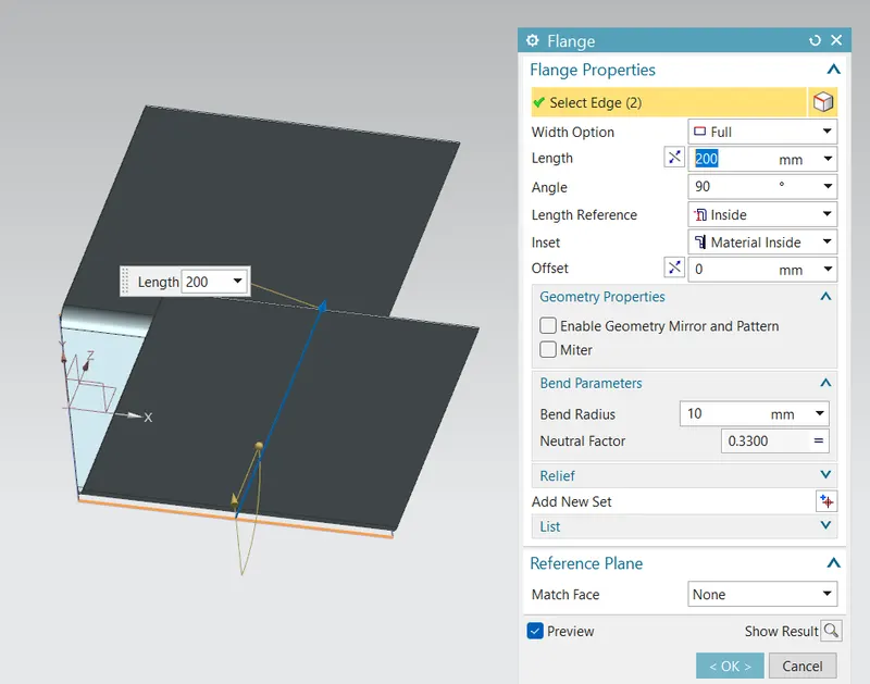
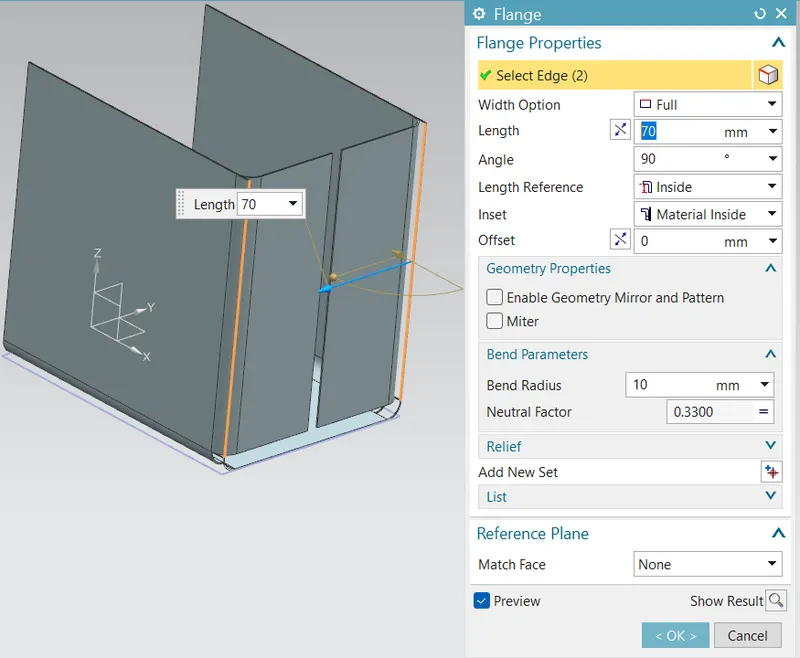
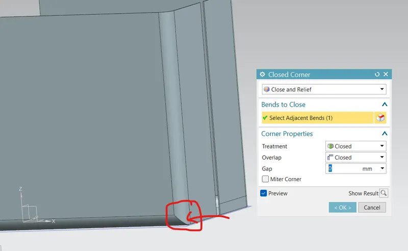
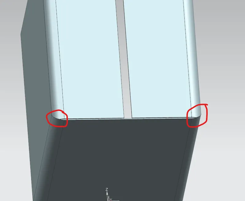
Step 2 : Closing the bottom corners
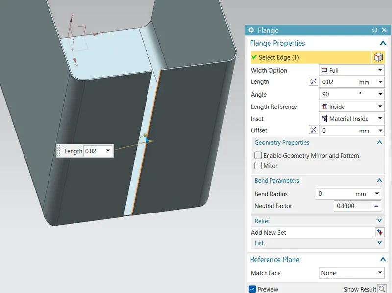
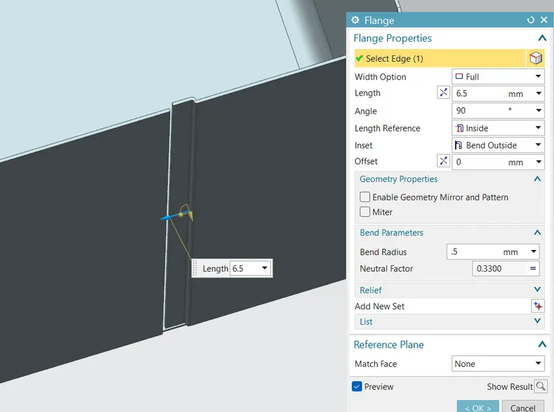
Step 3 : Closing the side wall by hemming.
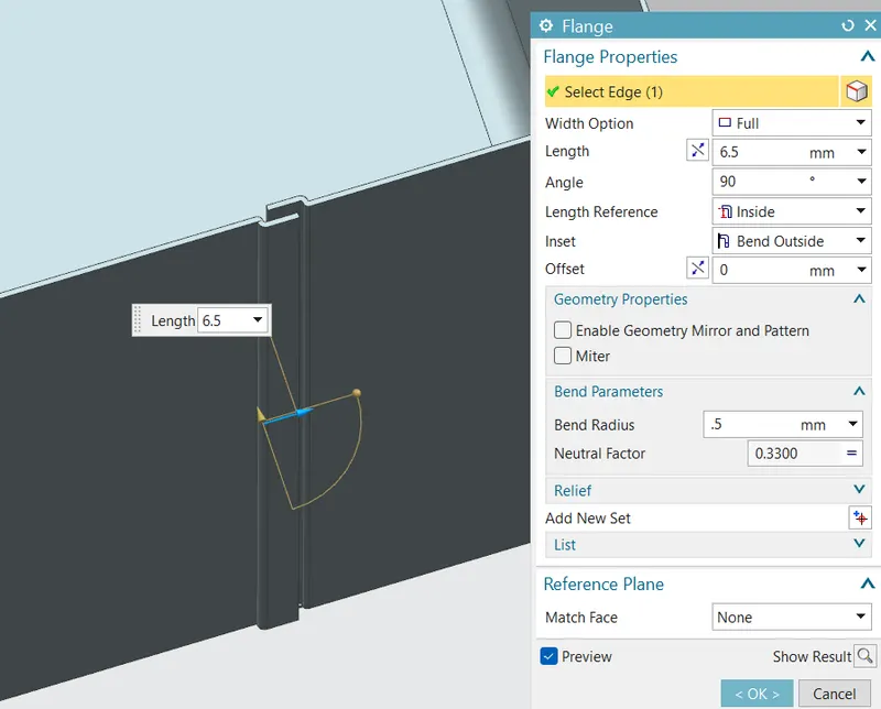
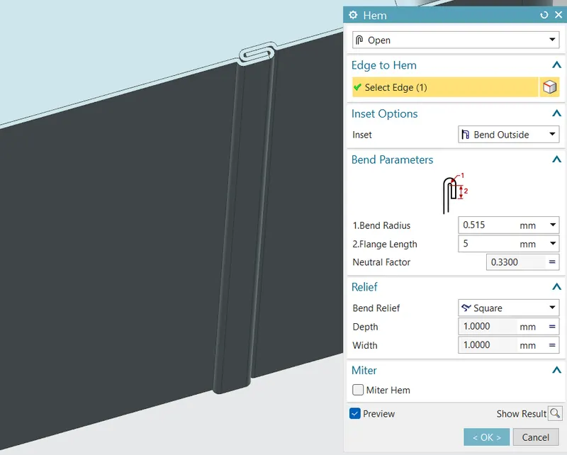
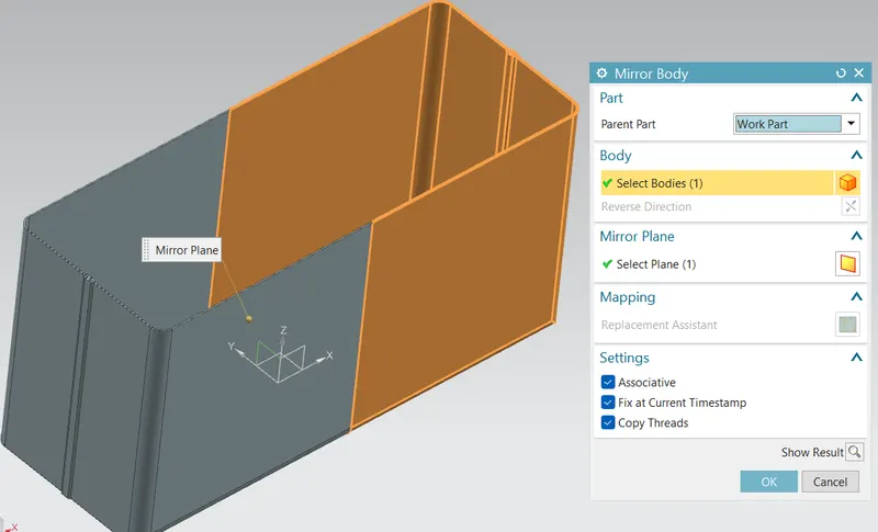
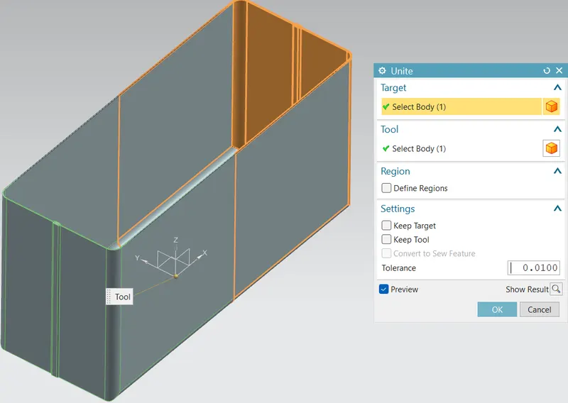
Step 4 : Mirroring the whole body with respect to ZY plane and uniting the body.
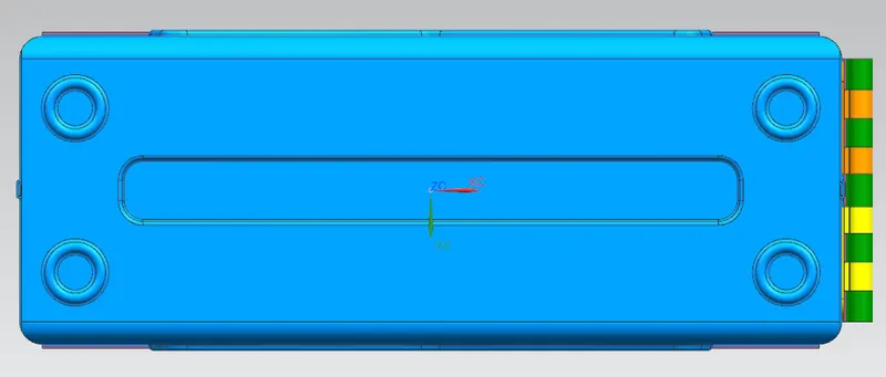
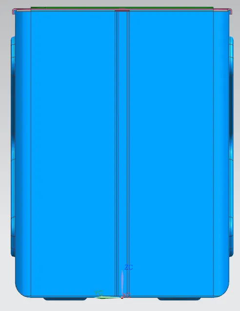
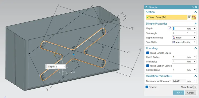
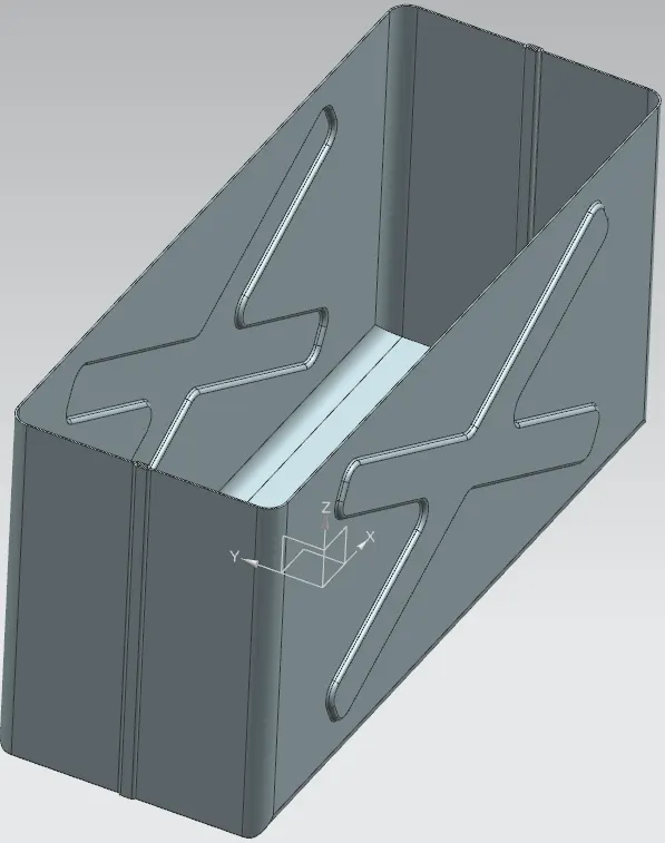
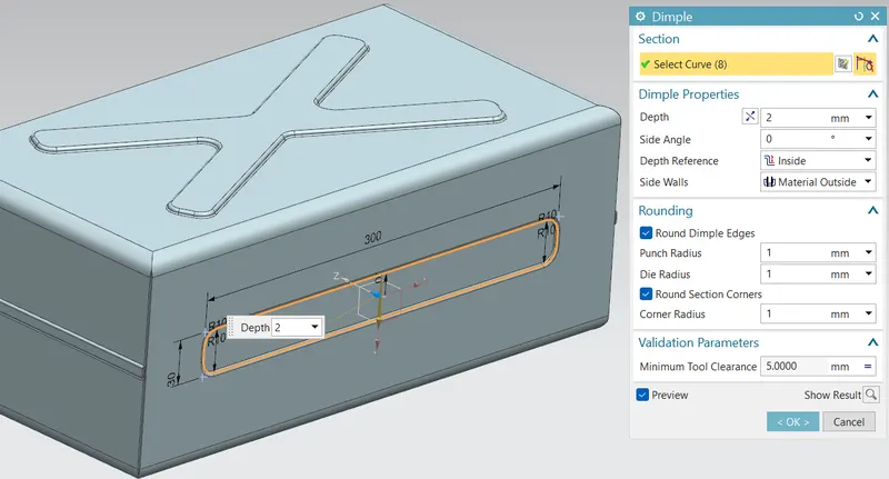
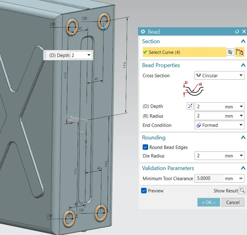
Step 5 : Creating emboss features on the two big side walls and base or bottom surface of the box for improving the strength. Beads are made on the base for proper resting or proper butting on the floor.
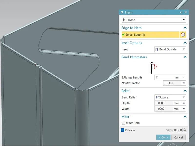
Step 6 : Hemming is provide on the top edges for strength and removing sharp edges.
- Added next part to the assembly named Box_LID.
- make the Box_LID as work part.
Designing Lid for the Box:
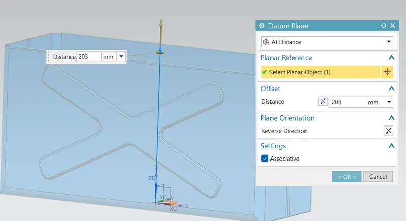
Step 1 : Made a plane considering the position will be above box top plane.
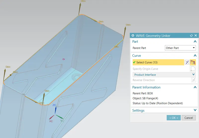
Step 2 : Using wave geometry linker extracted the top boundary of box.
Step 3 : Making sketch for the lid base using reference as the boundary extracted.
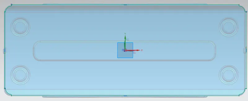
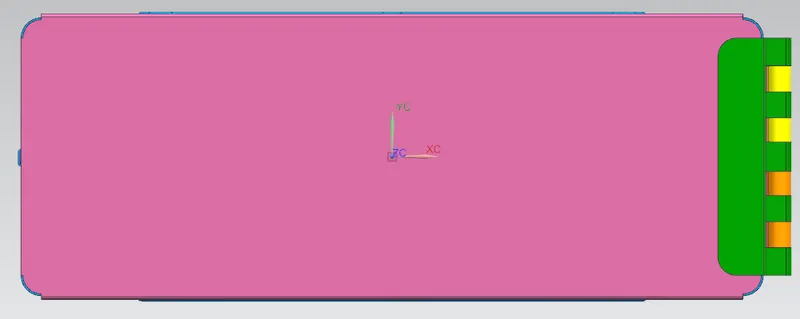
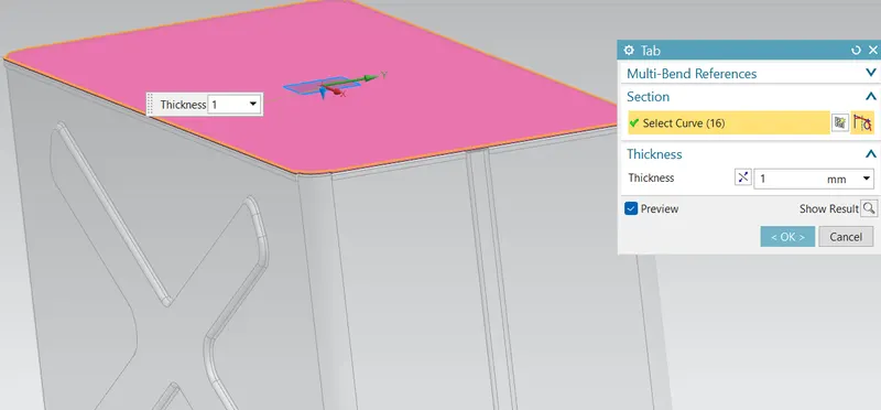
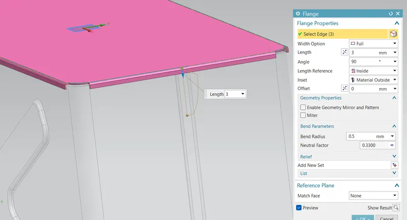
Step 4 : Using tab command made the base and added flanges on the sides.
- Adding new assembly file named Hinge_Assembly.
- In that Hinge_Assembly made new part named Box_Side_Hinge.
- made work part as box_side_hinge.
Box_Side_Hinge Designing:
Step 1: Extracted the surface from the box using 'Wave geometry linker' command where hinge meant to fix. and made a sketch for base of hinge. Made it a solid using tab command of thickness 1mm.
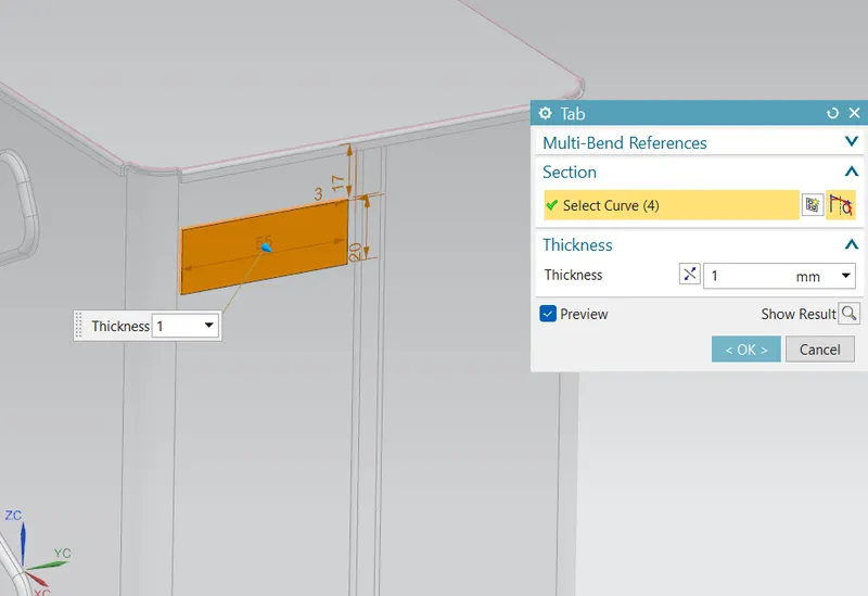
Step 2 : using break corner command removed its bottom edge corner.
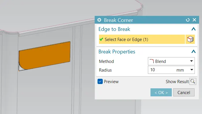
Step 3 : Added flanges two times in different angle as shown below.
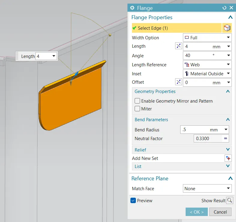
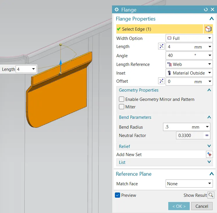
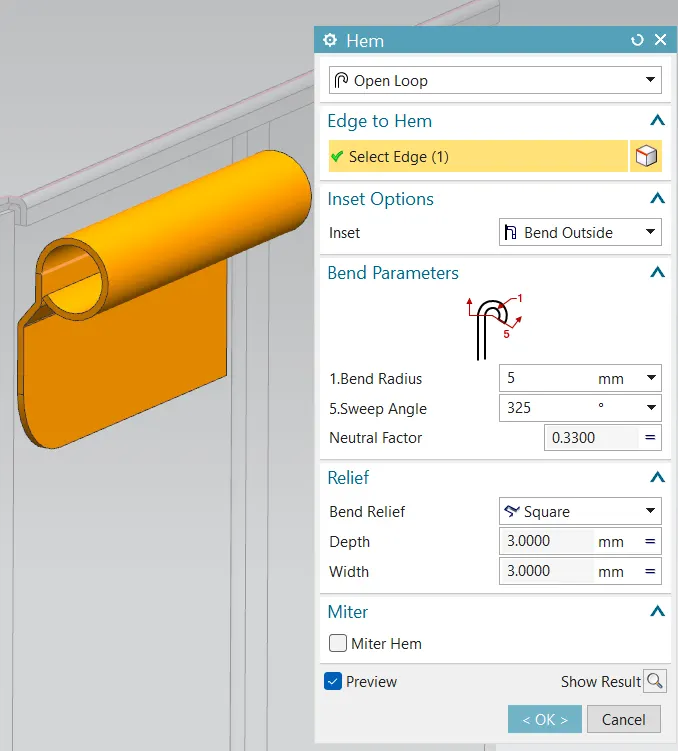
Step 4 : Using 'Hem' command made a cyclindrical roll and unbend all the sheet.
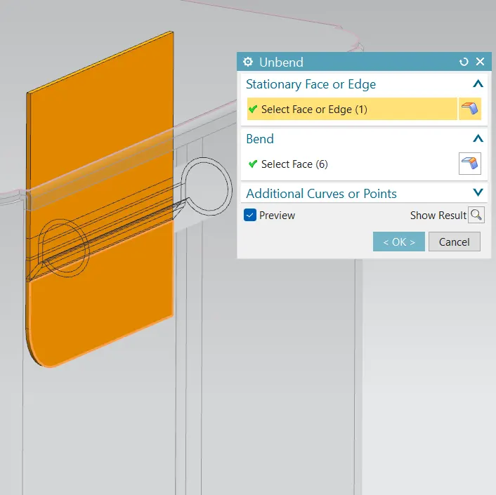
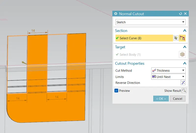
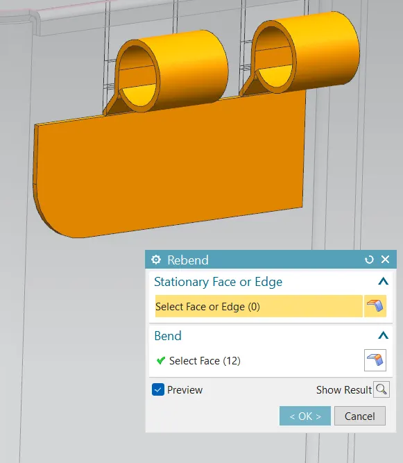
Step 5 : Made one sketch for the cut outs and using 'Normal Cutout' command made the cutouts as shown below. Rebend it again using rebend command.
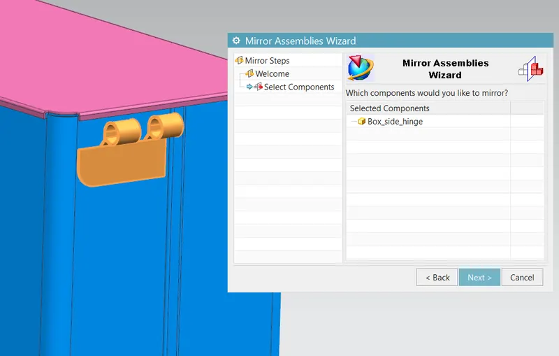
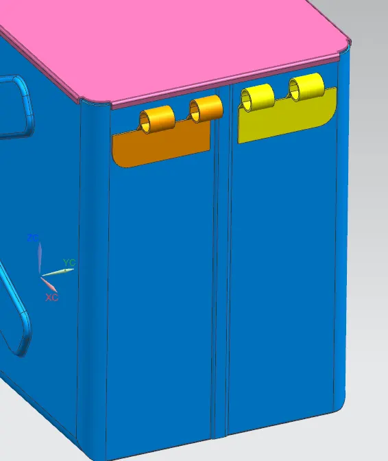
- Using Mirror assembly command made a mirror of the Box_side_hinge.
- Adde new part named Lid_side_hinge.
- And made work part.
Lid_side_hinge Designing:
Step 1 : Take extracted refernce surface as top srface of the LID, using 'wave geometry linker' command and made the sketch for the base. using tab command make it as solid body of thickness 1 mm as shown below pictures.
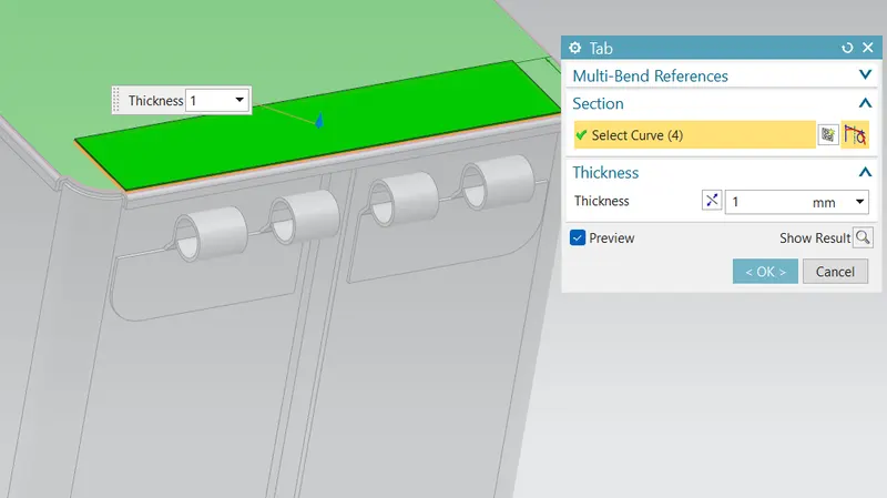
Step 2 : Made a flange extenesion at an angle, using 'flange' command, then created a rolled structure at the end using 'hem' command. as shown below.
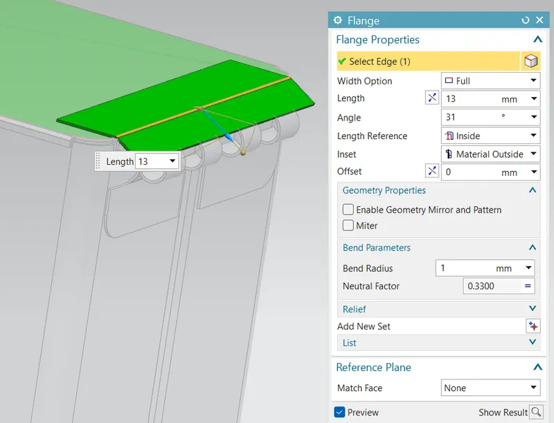
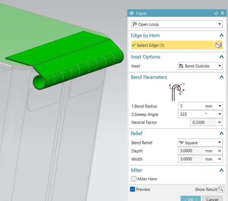
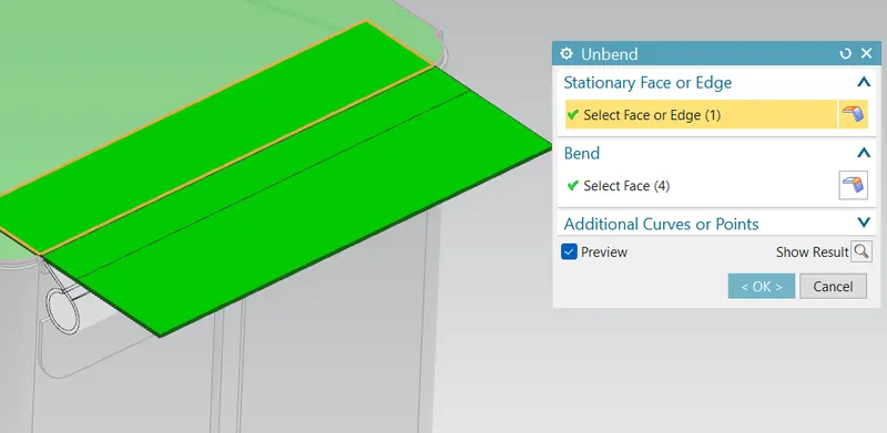
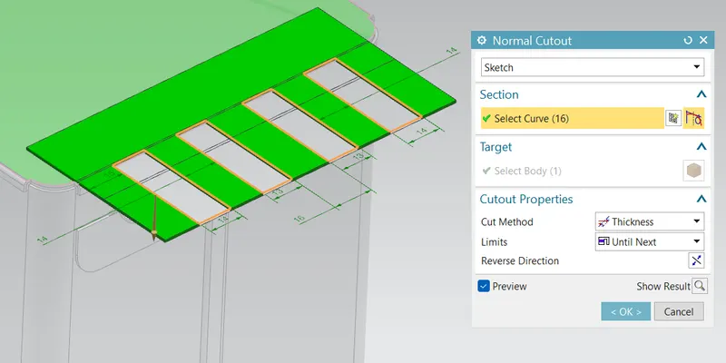
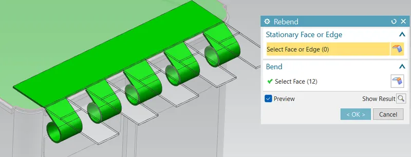
Step 3 : using unbend command made the sheet metal structure to a flat structure. created sketch on the surface for making the cut outs matching with box_side_hinge. then rebend to the previous structure.
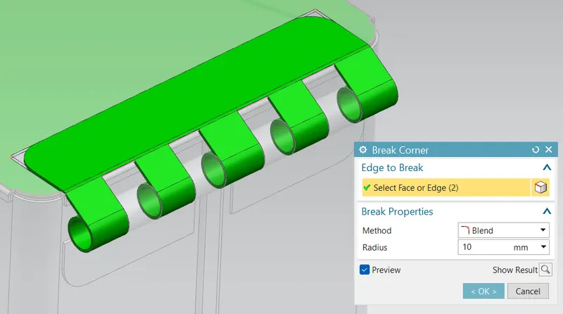
Step 4 : Removing the sharp corners
Conlcusion:
Box assembly designing has been done.