Advanced Sheet Metal Design Using NX Cad Challenge_2_Box Assembly
Advanced Sheet Metal Design Using NX Cad Challenge_2_Box Assembly
Objective: Write a detailed report on Sheet Metal Component with good explanation on Sheet Metal modelling tools applied throughout the modelling.
Design Methodology to Create Box
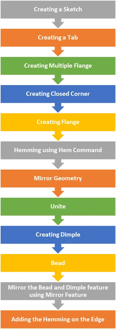
Procedure to create sheet Metal Box:
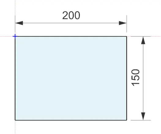
Sketch
Creating a rectangular Box of DIMN 200mm X 150mm.
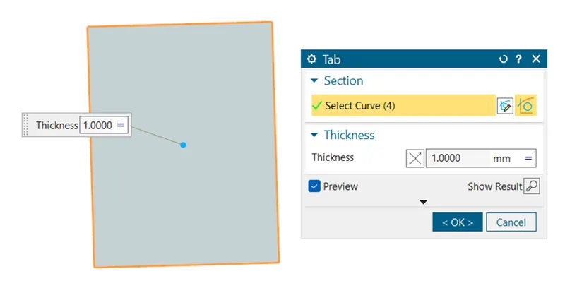
Tab
Creating a Tab of thickness 1mm for the above rectangular sketch.
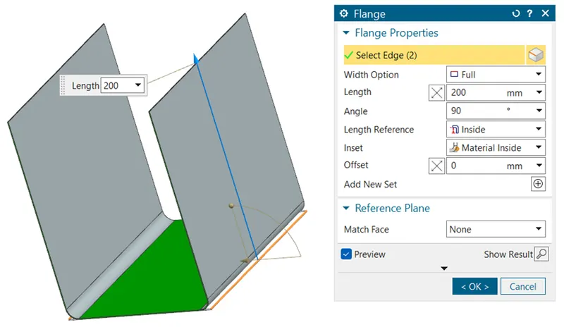
Flange
Creating a Flange of length 200mm
Flange
Create a Flange of length 70mm
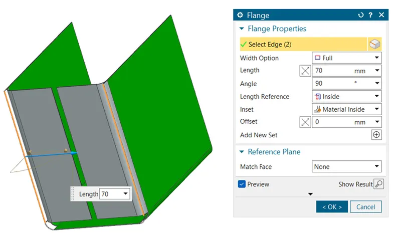
Closed Corner
Select the edge of Tab and Flange and apply closed corner to close edge of Box.
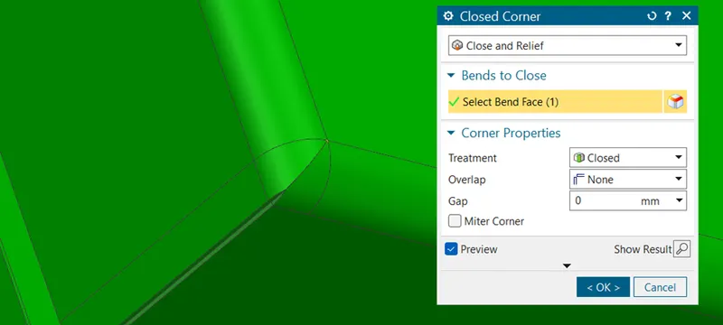
Flange
Select the flange command and create a flange of 0.6mm on the edge at 90°.
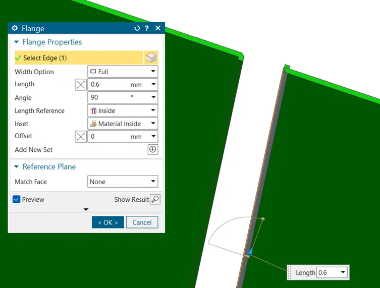
Create 2 more Flange of 8mm at 90°.
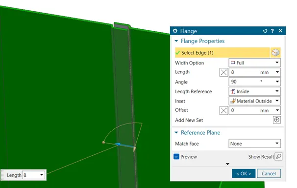
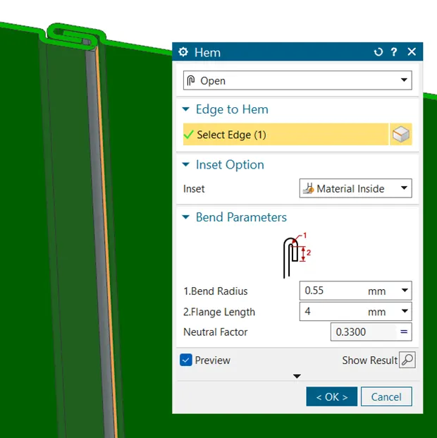
Hem
Apply the hemming on both the flanges, in order to close the loop.
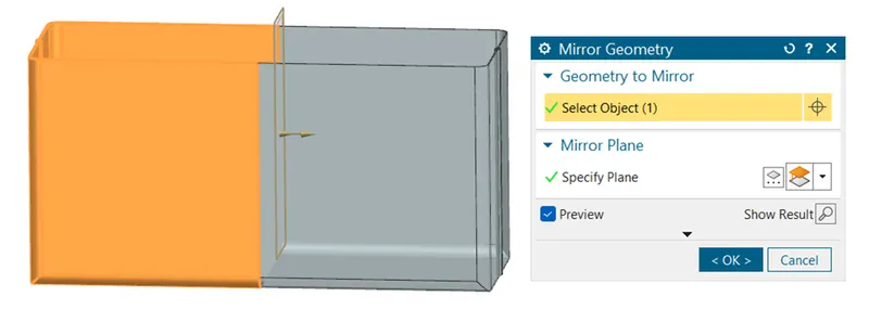
Mirror Geometry
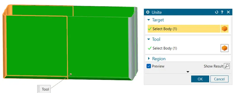
Once the one side of the profile is ready we will mirror the object and later we will unite it to make a single body.
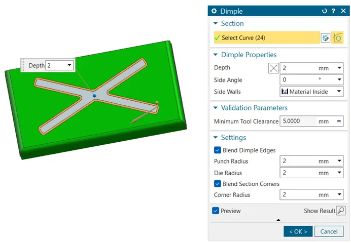
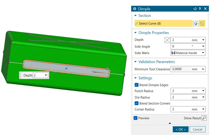
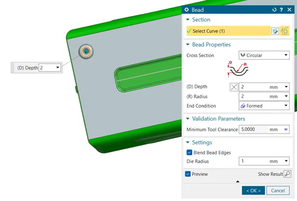
Dimple & Bead
We will draw the pattern on the surface and later will make a protrusion of 2mm.
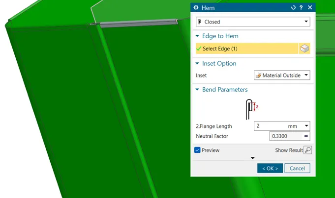
Hem
In avoid the sharp edges on edge of the Box, we will apply the hemming on that edge.
3D Views
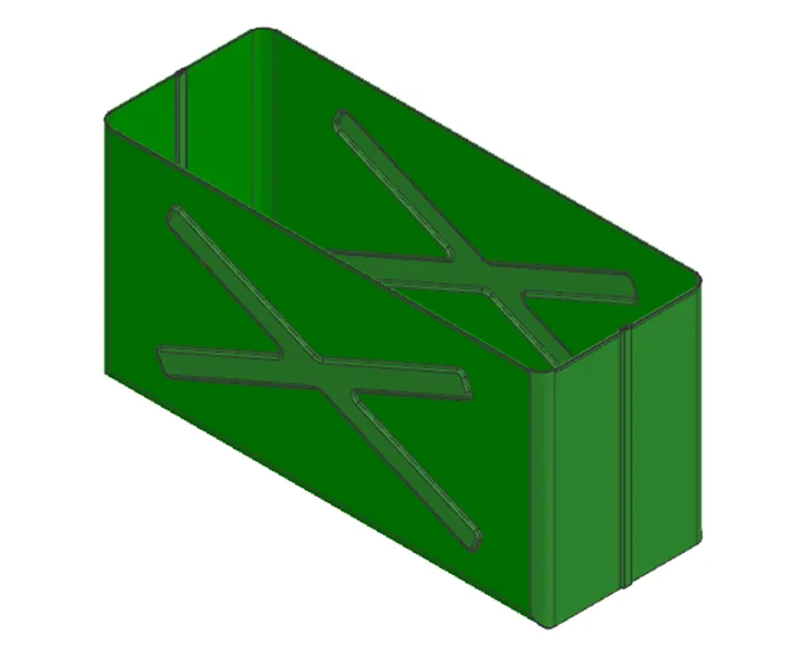
Isometric View
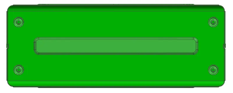
Top View
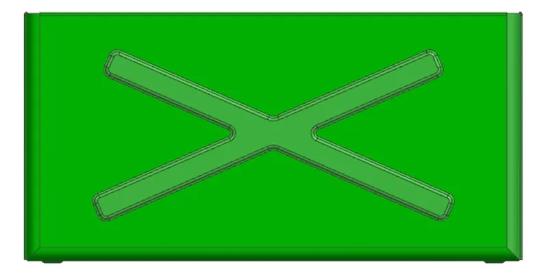
Front View
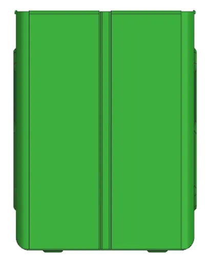
Right Side View
Design Methodology to Create Lid
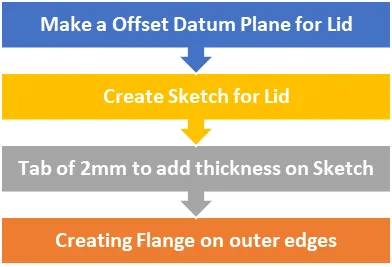
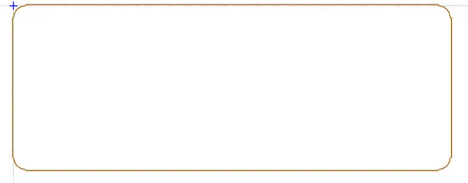
Sketch
Create a sketch with reference of the Box.
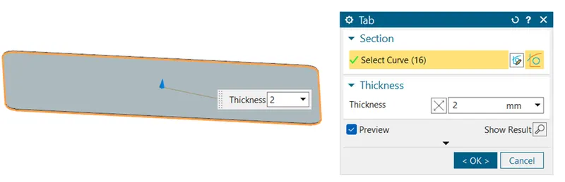
Tab
Creating a 2mm thickness of Sketch
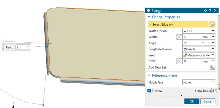
Flange
Create a flange of 3mm on the edge of the corner
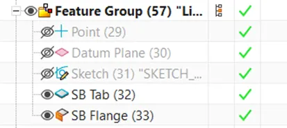
Feature Tree of Lid
3D Views of Lid
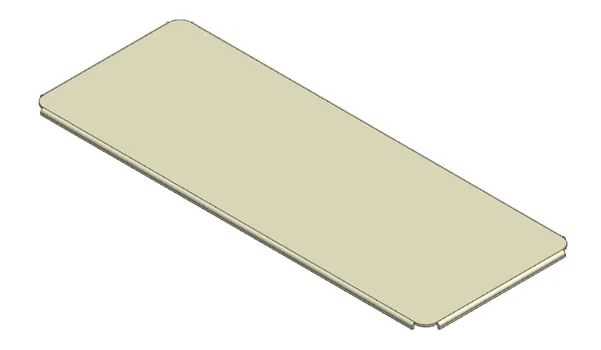
Isometric View
Front View

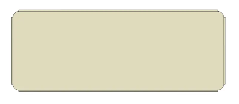
Top View
Right Side View

Design Methodology to create Lower Hinge
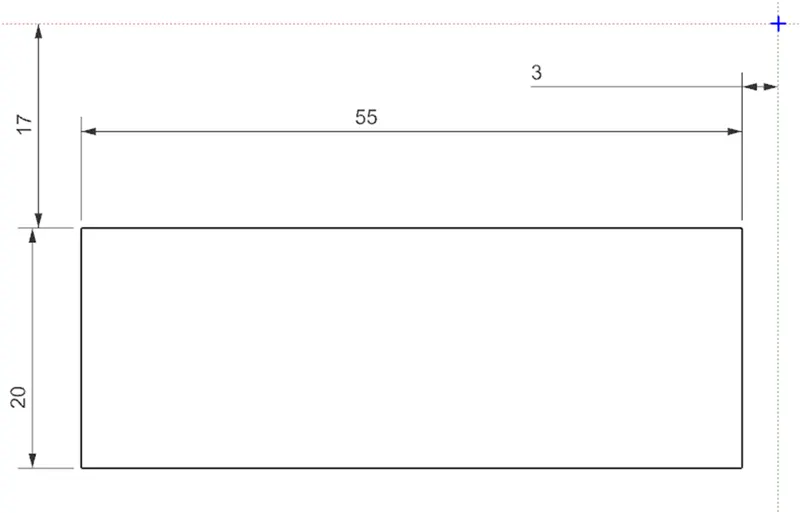
Sketch
Create a sketch of rectangular box of DIMN 20mm X 55mm.
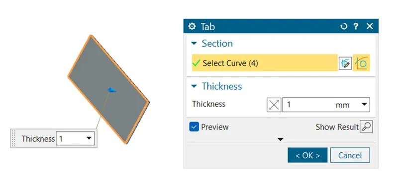
Tab
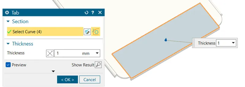
Creating a Tab of thickness 1mm for the above rectangular sketch.
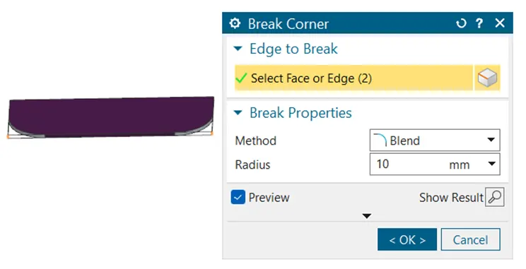
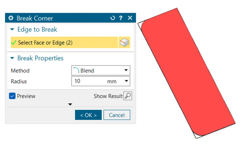
Break Corner
To smoothen the sharp edges of sheet metal we will use Break Corner
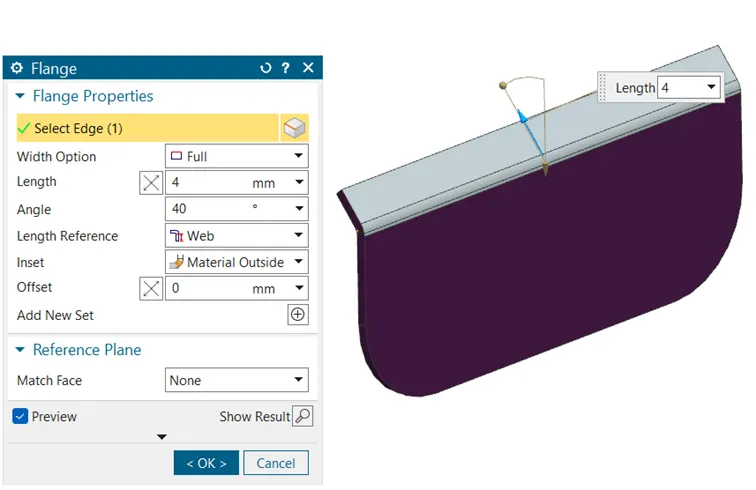
Flange
Creating a Flange of length 4mm at angle of 40°.
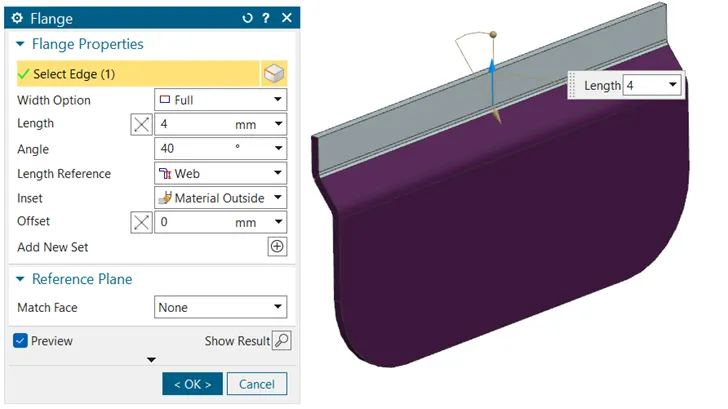
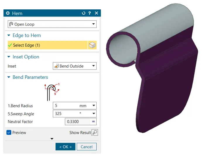
Hem
To make a round profile, we will use Hem command in open loop.
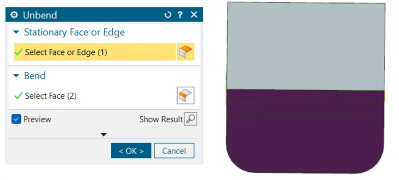
Unbend
Unbend the Sheet metal (Straighten)
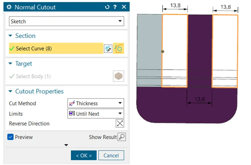
Normal Cutout
Make a sketch for a normal cutout to remove the material.
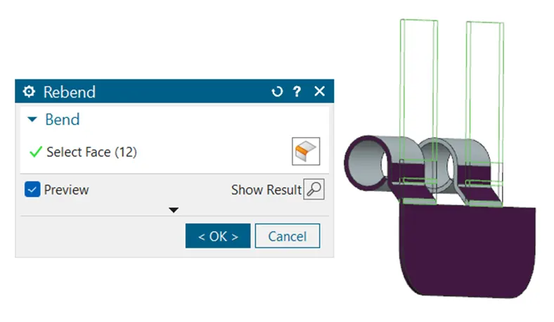
Rebend
To roll back the previous bended profile we will use Rebend Command.
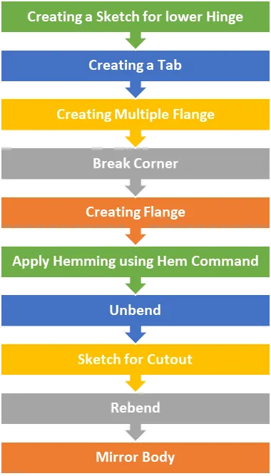
Feature Tree of Lower Hinge
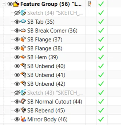
3D views of Lower Hinge
Isometric View
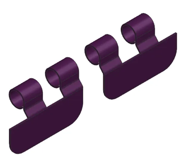
Front View

Top View

Right Side View

Design Methodology of Upper Hinge
Tab
Creating a Tab of thickness 1mm for the above rectangular sketch.
Break Corner
To smoothen the sharp edges of sheet metal we will use Break Corner.
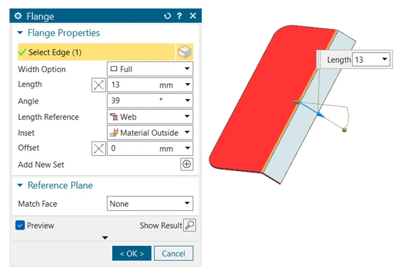
Flange
Creating a Flange of length 13mm at angle of 39°.
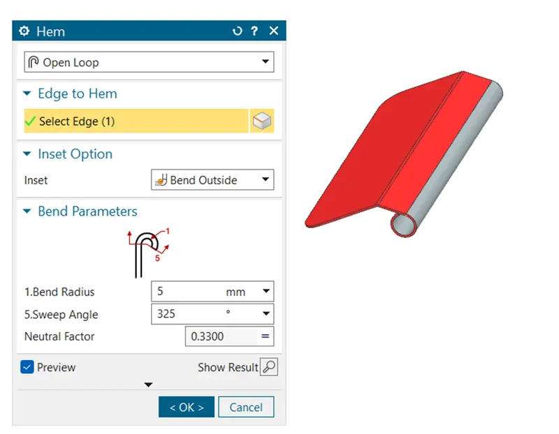
Hem
To make a round profile, we will use Hem command in open loop.
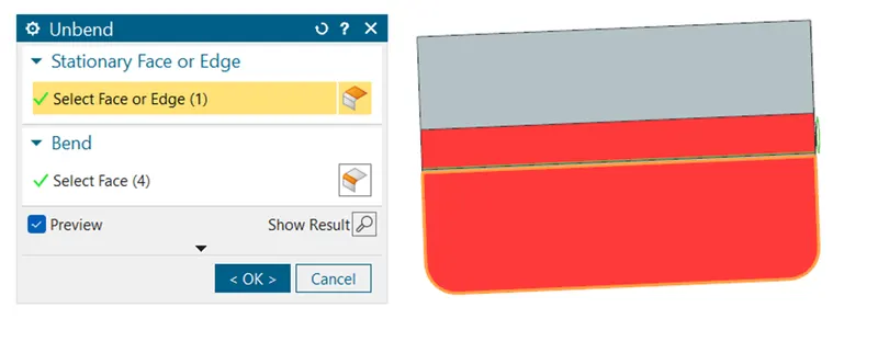
Unbend
Unbend the Sheet metal (Straighten)
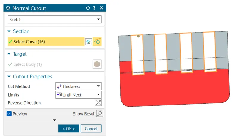
Normal Cutout
Make a sketch for a normal cutout to remove the material.
Rebend
To roll back the previous bended profile we will use Rebend Command.
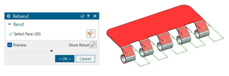
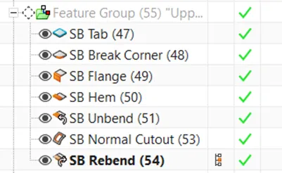
Feature Tree of Upper Hinge
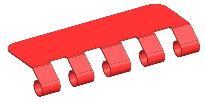
3D View of Upper Hinge
Isometric View
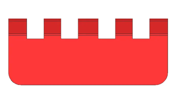
Top View
Front View
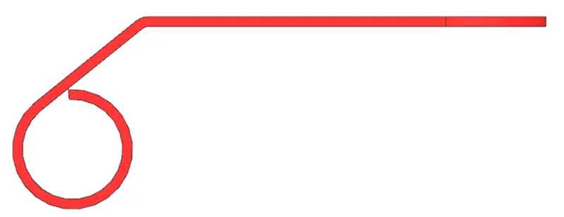
Right Side View
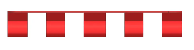
Final 3D View
Isometric View
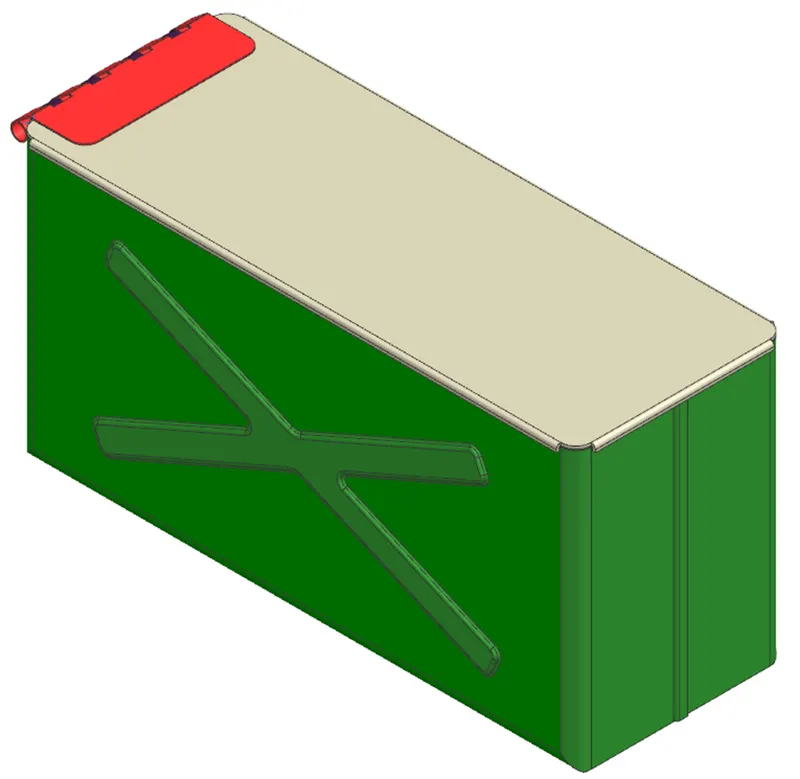
Front View
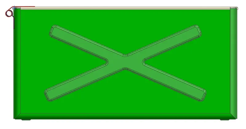
Top View
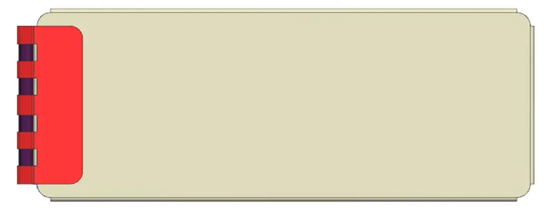
Right Side View
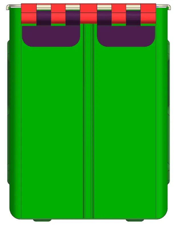
2D Drawing
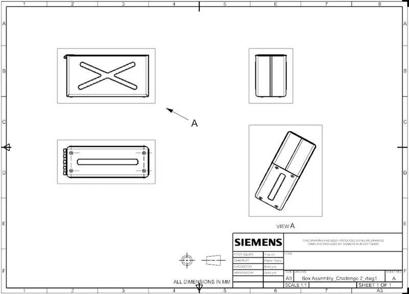
Conclusion:
In this challenge we have learn the multiple sheet metal command, through which we have drafted multiple components like Box, Lid, Lower Hinge and Upper Hinge.