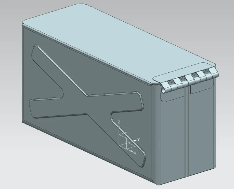
Advanced Sheet Metal Design Using NX Cad Challenge_2_Box Assembly
Box assembly
OBJECTIVE:
To Write a detailed report on Sheet Metal Component with good explanation on Sheet Metal modelling tools applied throughout the modelling.
Introduction:
Sheet metal design software considers the fabrication methods needed for manufacturing. As you create flanges and add bends, the sheet metal design software will accurately represent the flat pattern required. The flat pattern can be used to document and manufacture associatively as the design changes. Here in this project we are dealing with the Sheet metal designing using the software Siemens Nx cad.
Design methodology / approach:
The box assembly designed for this project consists of features like tab, cut-outs, bends, flanges, hem flanges, dimples, and beads. The design methodology used for this project is summarized in below flowchart.
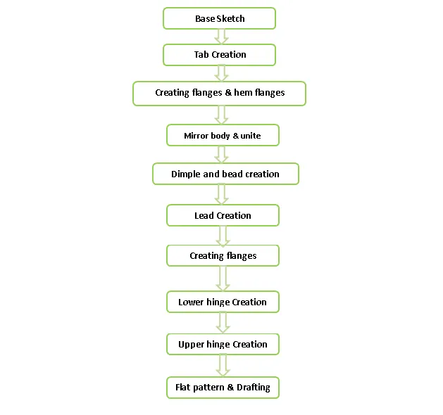
Description:
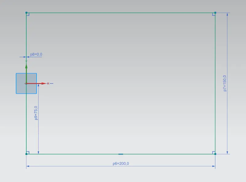
- SKETCH: This is used to create a basic sketch of the design on selecting the desired plane, then later it can be modeled for the requirement.
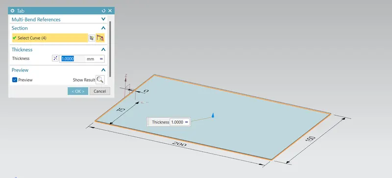
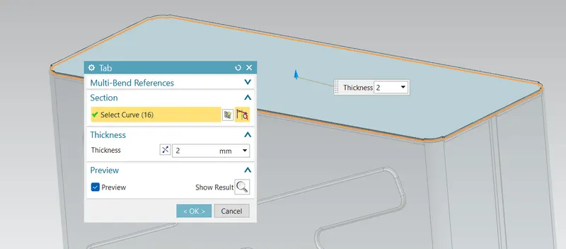
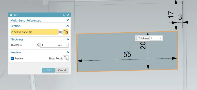
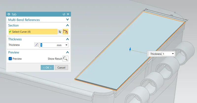
- TAB: Creates a base feature by extruding a sketch along a vector by a thickness value or adds material to a planar face. Additional planar sections can be added to generate bends as part of the base feature.
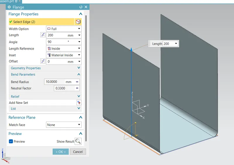
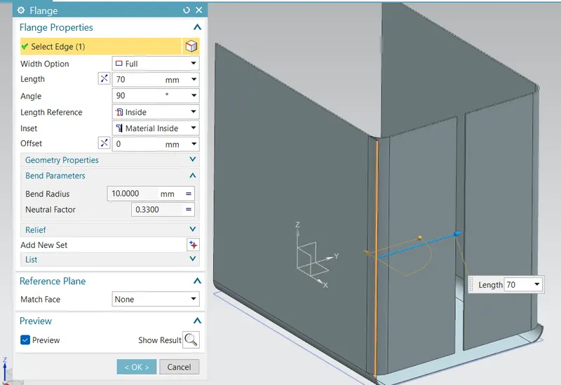
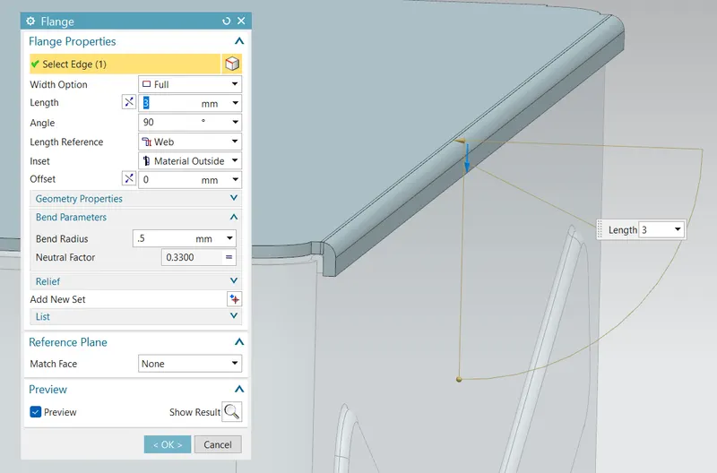
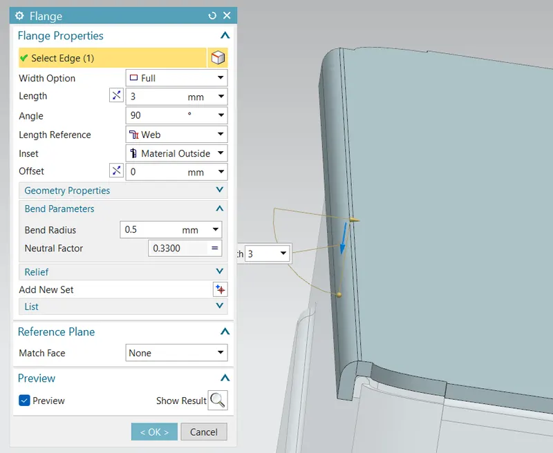
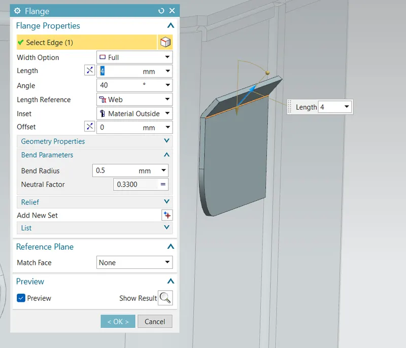
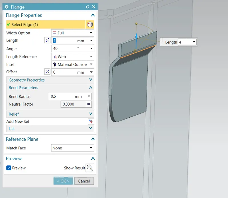
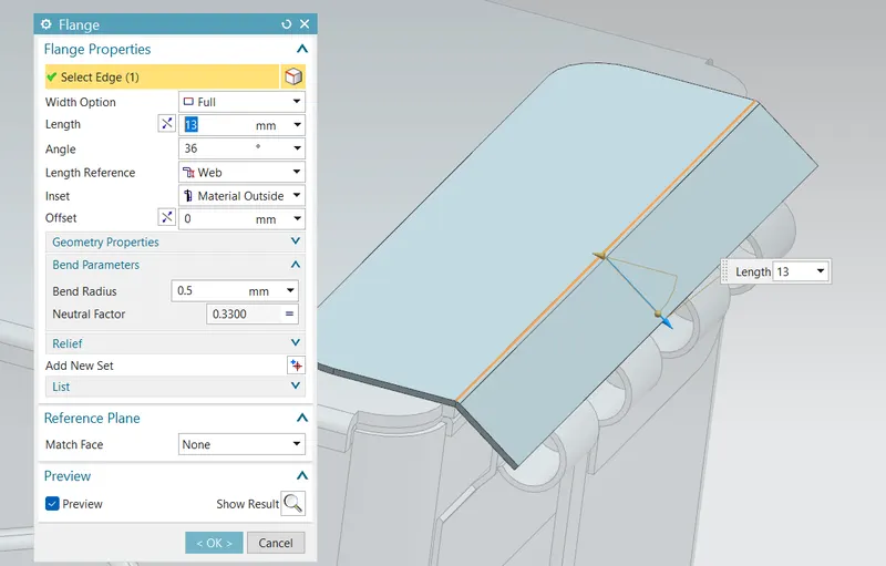
- FLANGE: Adds a flat flange at an angle to a planar face and adds a bend between the two.
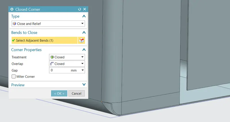
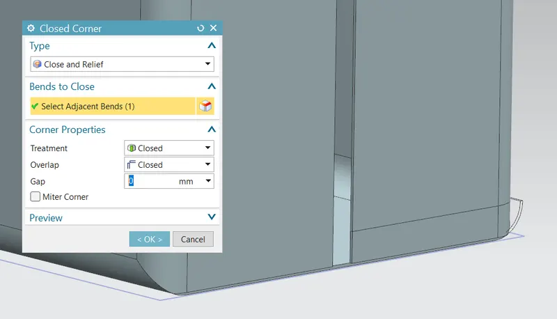
- CLOSED CORNER: This command is used to modify two flanges in one operation and to close the corner where the two flanges meet.
-
FLANGE FOR FASTENING: For the fastening purpose by the bending of edges, a flange without length is first made and another bend flange is used to bend it outwards to obtain the following result.
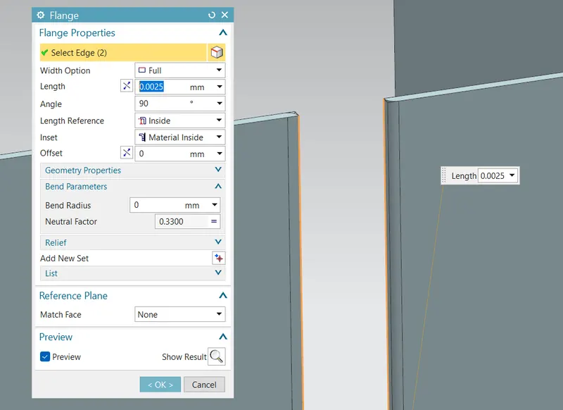
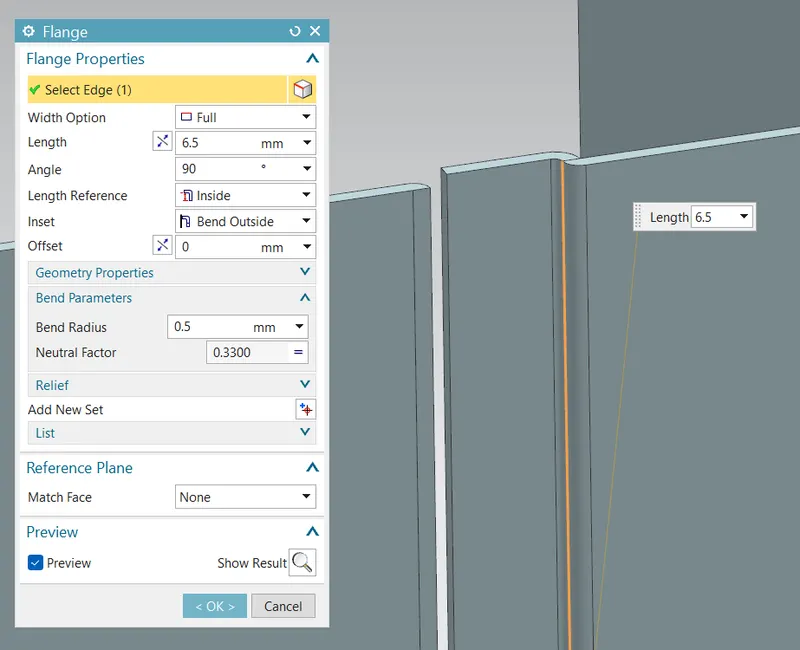
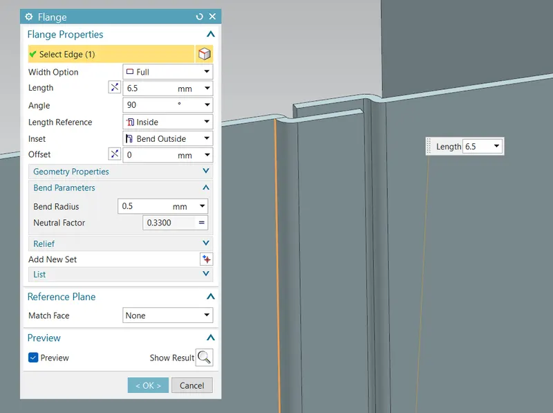
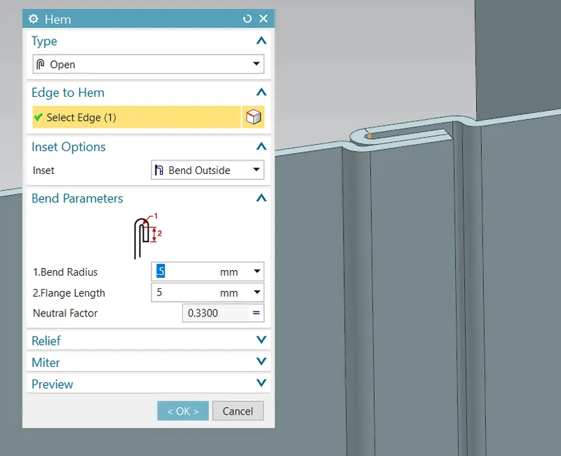
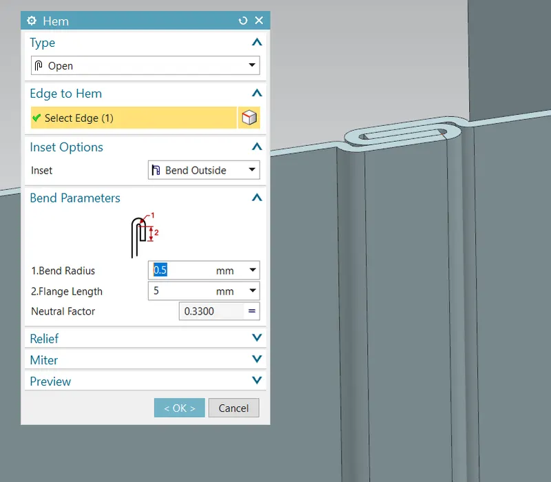
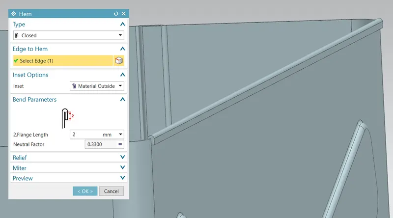
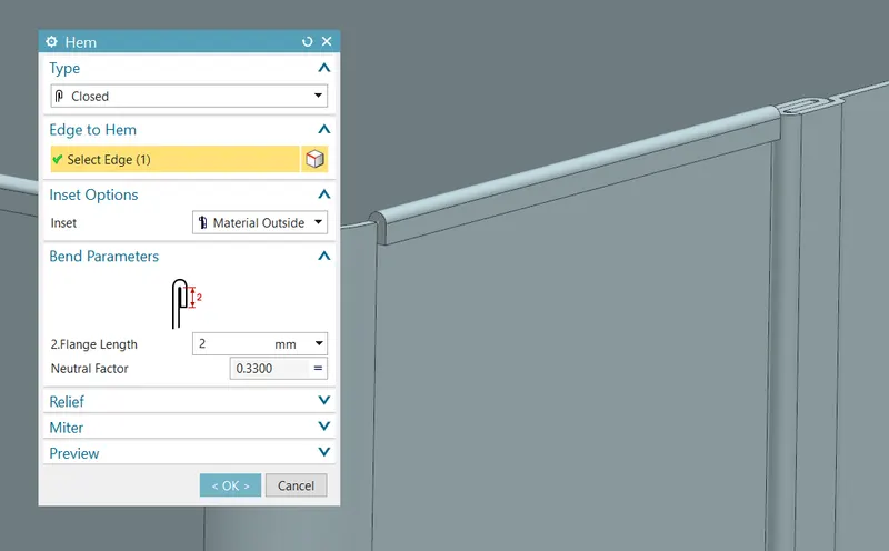
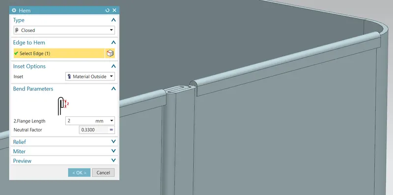
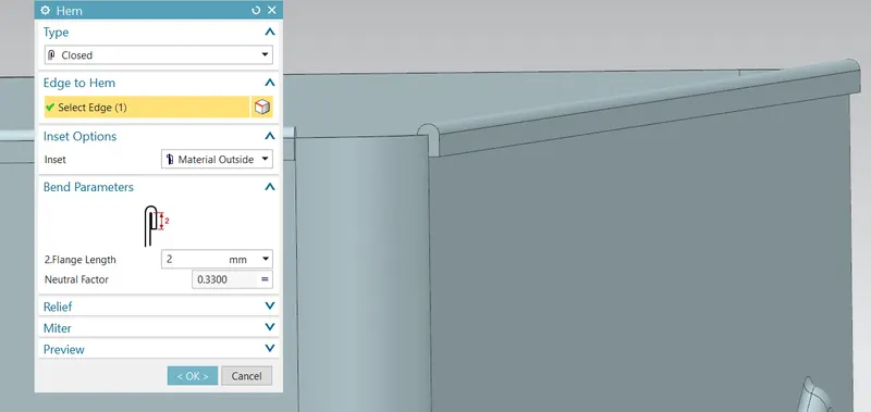
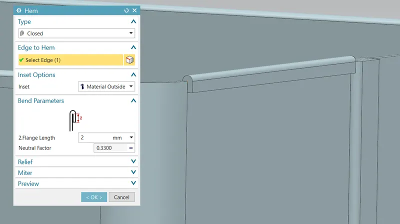
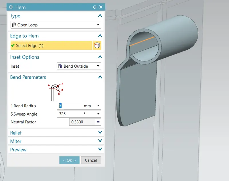
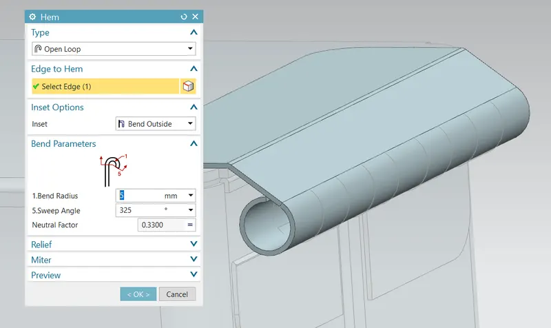
- HEM FLANGE: This command is used to modify an edgeof a sheetmetal part by folding it on to itself for the purpose odf safe handling or to increase edge stiffness.
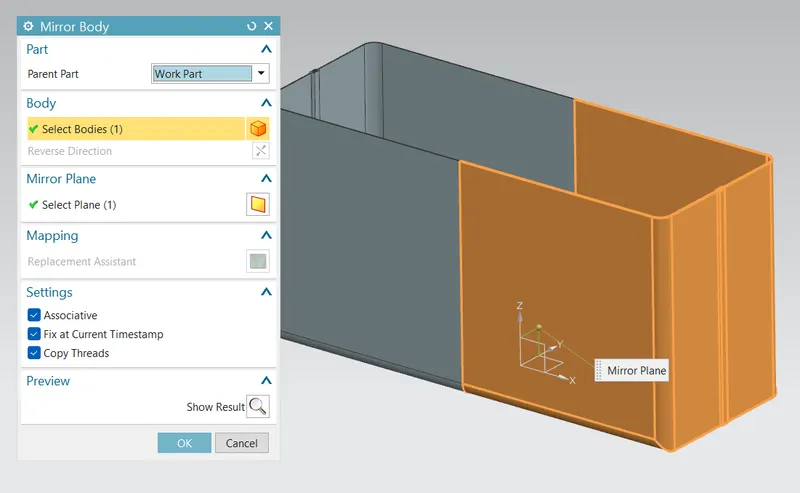
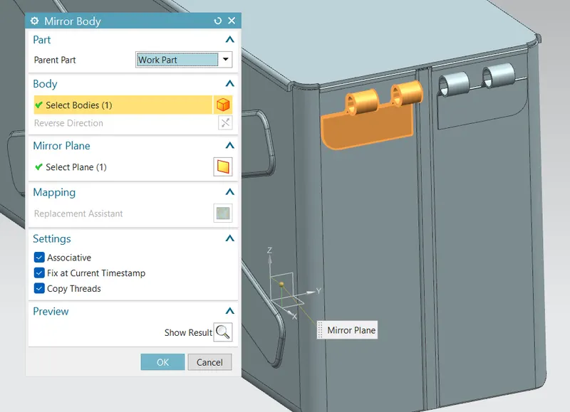
- MIRROR BODY: This command is used to mirror the part w.r.t the required axis.
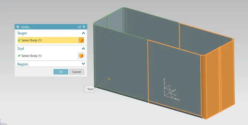
- UNITE: This command is used to combine the two parts into one part.
- SKETCH FOR DIMPLE:
Sketch 1:
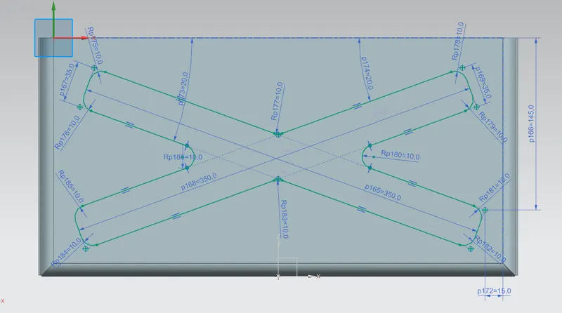
Sketch 2:
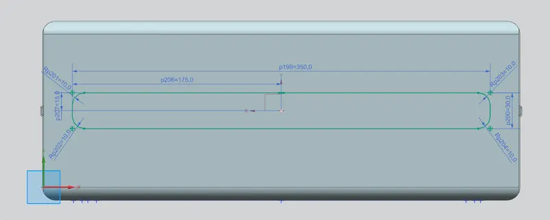
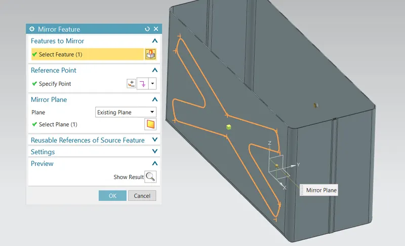
- MIRROR FEATURE: This command is used to mirror the required sketch to other side with reference to the axis.
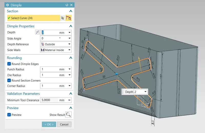
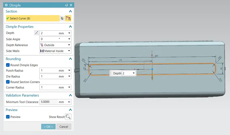
- DIMPLE: This command is used to lift an area of the model inside the sketch that stimulates a stamping tool.
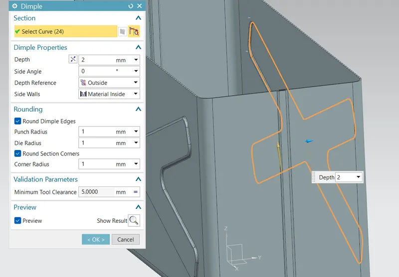
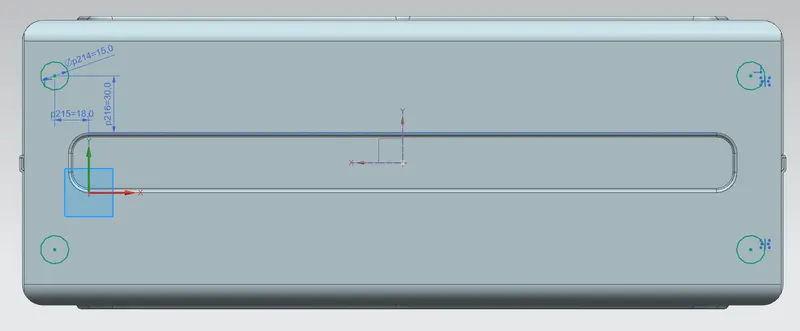
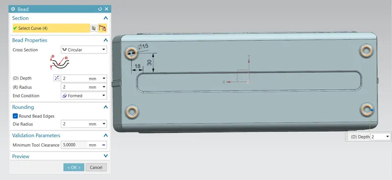
- BEADS: This command is used to lift material along contour of a sketch that stimulates a stamping tool. Bead can also be created to stiffen shhet material.
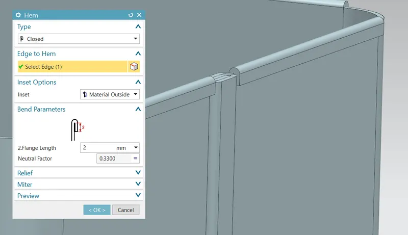
- HEM FLANGE: At this stage, the hem flange is applied at the top edge of the side flanges, and the flanges normal to the YZ plane.
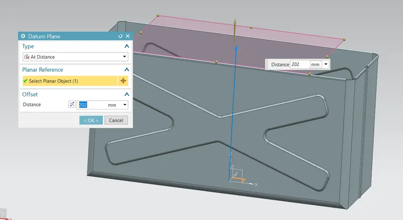
- DATUM PLANE: This feature is used to project the plane at a certain distance by giving the distance.
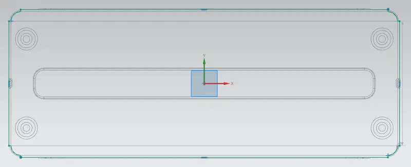
- LID CREATION: The sketch is created taking the reference of the edges from the top view of the box design at this stage.
Sketch:
Tab:
Flange:
- HINGE CREATION:
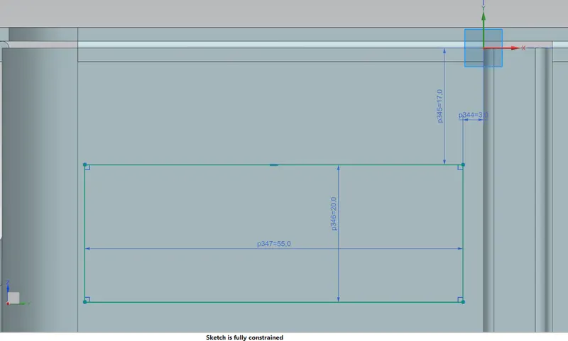
Sketch:
Tab:
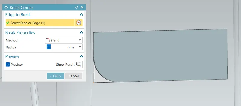
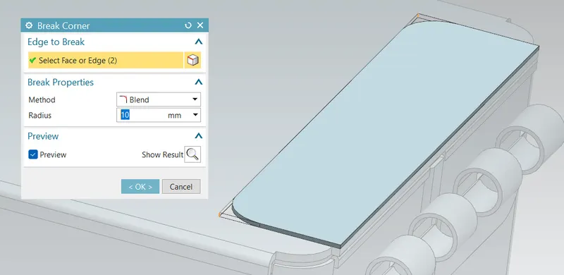
Break corner: This feature breaks the sharp edges in the corners and makes it round or adds chamfer.
Flange:
Hem flange:
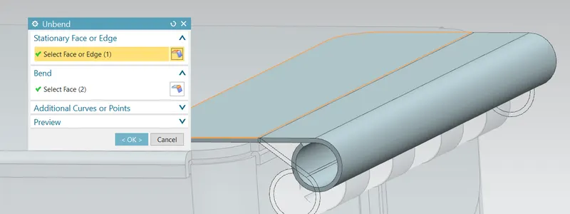
Unbend: This command is used to faltten the 3D model by selecting one stationary face.
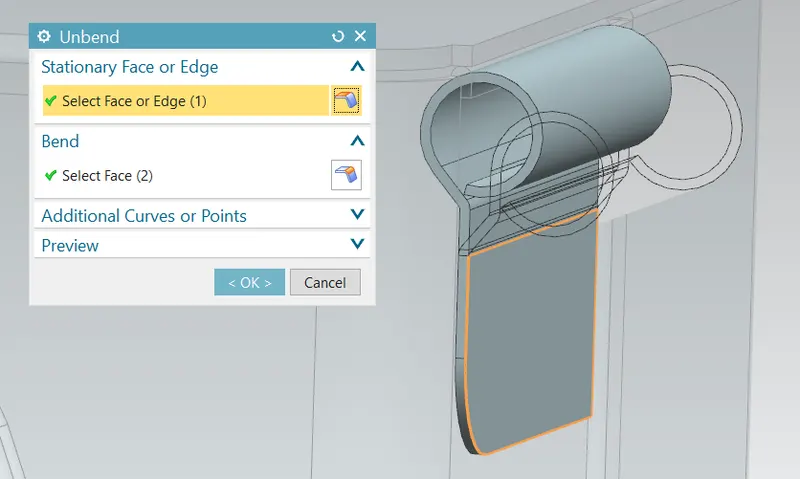
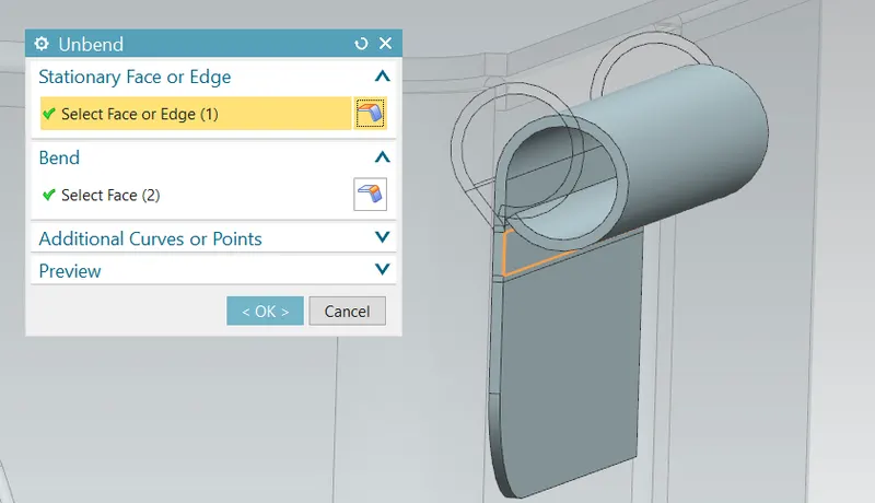
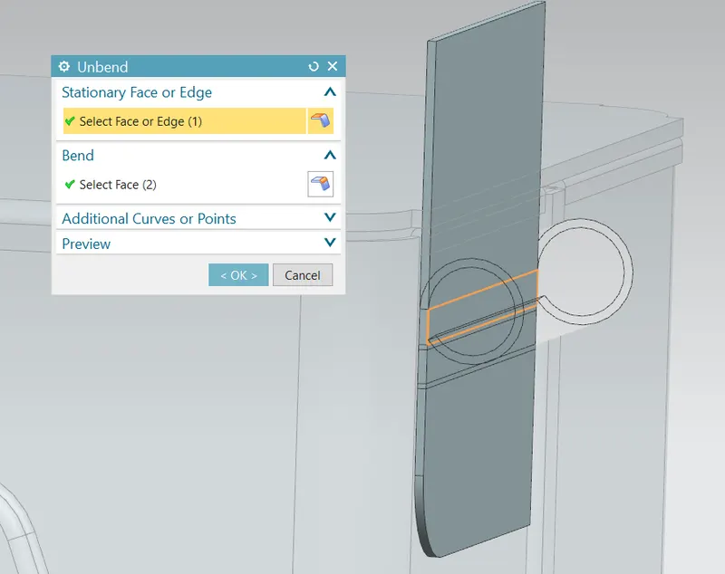
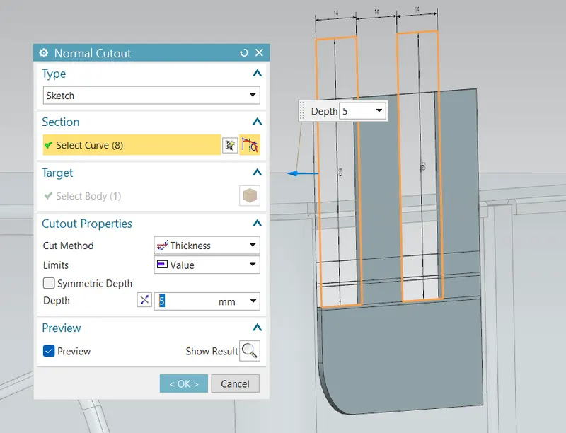
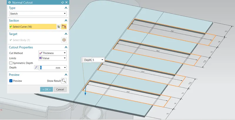
Normal Cutout: This command is used to remove the unwanted material w.r.t to the sketch.:
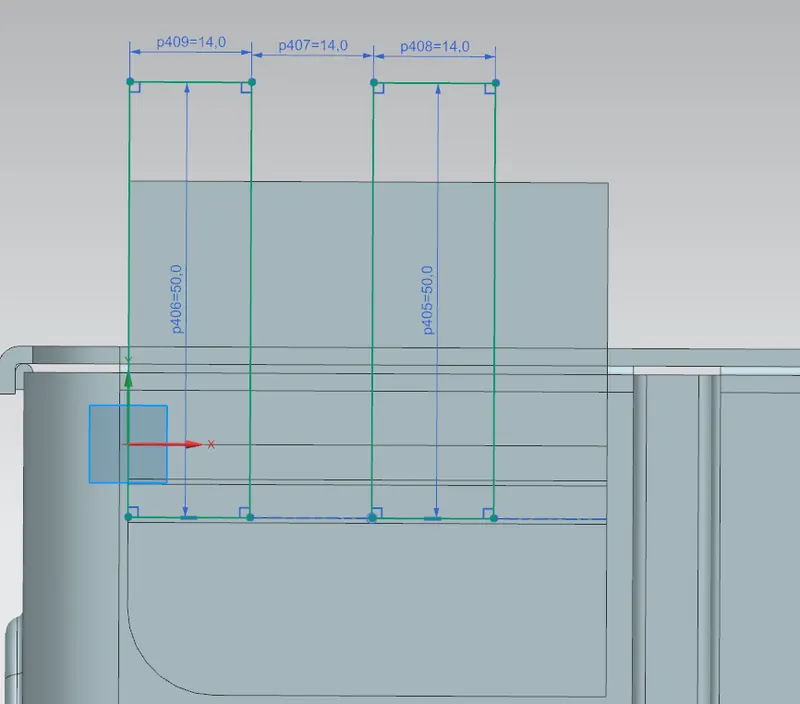
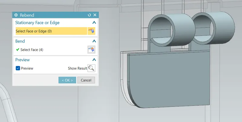
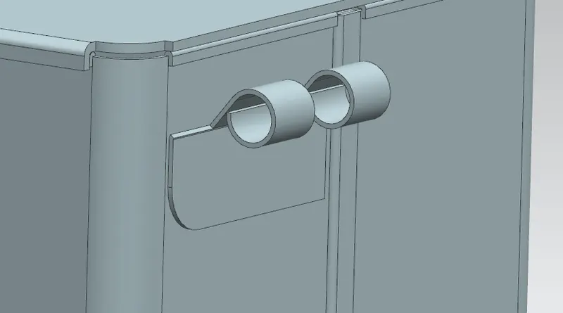
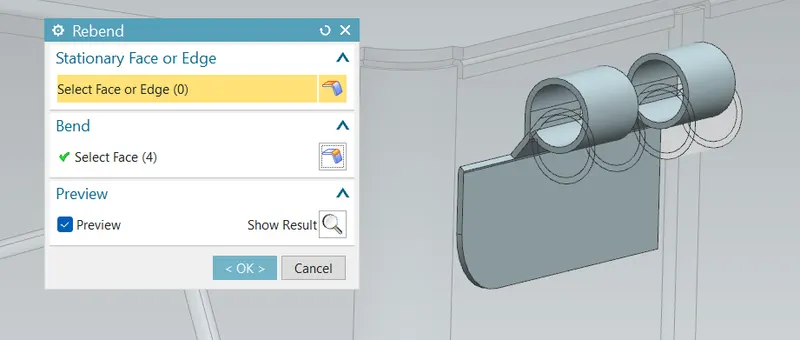
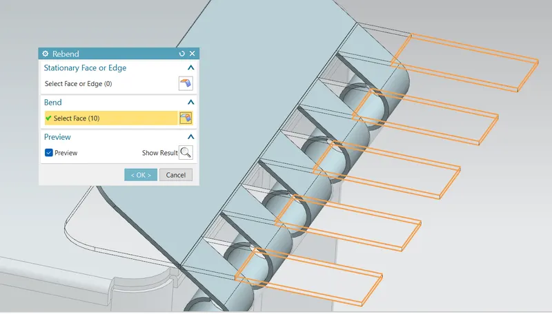
Rebend: This command is used to rebend the flattern sheet material.
Mirror body:
- UPPER HINGE CREATION:
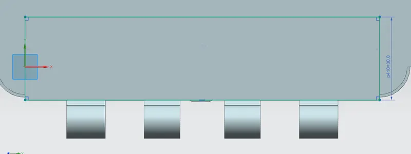
Sketch:
Tab:
Breakcorner:
Flange:
Hem flange:
Unbend:
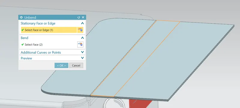
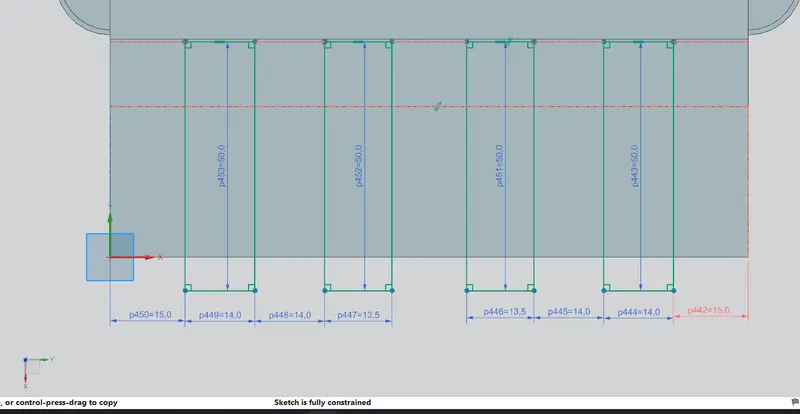
Sketch:
Normal cutout:
Rebend:
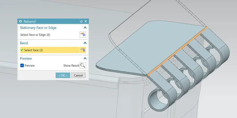
- FLAT PATTERN: It is the representation of the entire sheet metal component in the 2D form of the flat sheet metal with all the bends, cut-outs, holes, and additional features in the form of lines or edges.
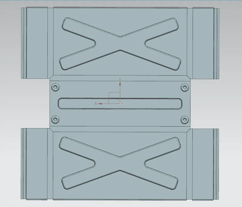
Final 3D models:
Front view:
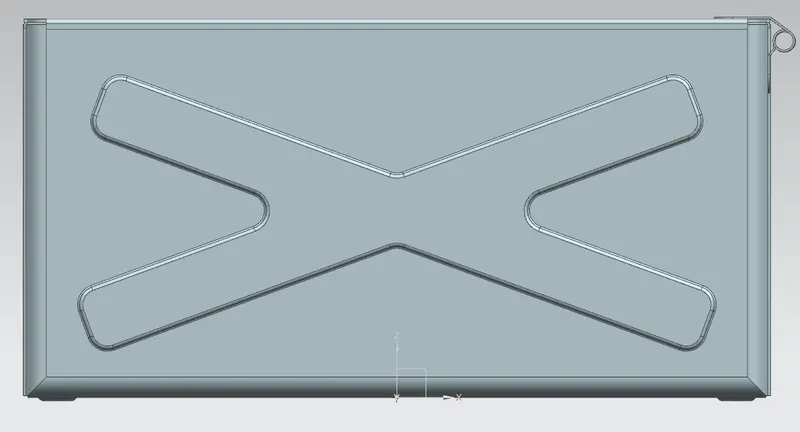
Top view:
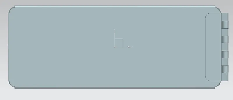
Left view:
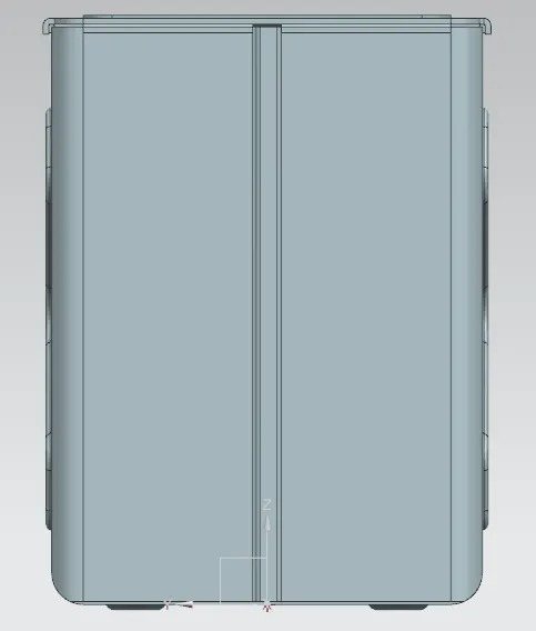
Right view:
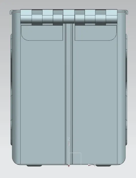
Bottom view:
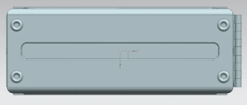
Isometric view: