Advanced Sheet Metal Design Using NX Cad Challenge_2_Box Assembly
Title:- Advanced Sheet Metal Design Using NX Cad Challenge_2_Box Assembly.
Objective:- To design a Box assembly using Siemens NX Sheet metal application.
Introduction:- Sheet metal is metal formed by an industrial process into thin, flat pieces. Sheet metal is one of the fundamental forms used in metal working and it can be cut and bent into a variety of shapes. Countless everyday objects are fabricated from sheet metal.A sheet metal Box Assembly was selected for this project to understand the basics of Sheet metal application in Siemens NX. The box assembly has some important features like flange, dimple, normal cutouts etc. The box assembly is a basic component which can be used as a CPU cover and other electronic components etc.
Description:-
NX Cad 12.0 software tool is opened and click new in the quick access tool bar.
A new modal popup appears. Choose Sheet metal and save the part names Box_Design.
Select the XY plane. And draw a rectangle of 200*150mm.
Using a tab feature select the drawn rectangle and create the tab.
Create a flange with a length of 200mm on the both sides.
Now create a flange on the newly created flange of 70mm length.
Use the closed corner feature to close the open spaces in the parts created.
Create a flange with bend radius of 0.0019999mm and bend radius of 0mm.
Create a flange of length of 6.5mm and bend radius of 0.5mm.
Create the flange on the other flange part as done in step 8 and 9.
Use hem feature to adjust on the bend in outside option and adjust as per the convienence.
Use mirror body feature for the body to replicate on the other plane.
Unite feature to unite the both parts.
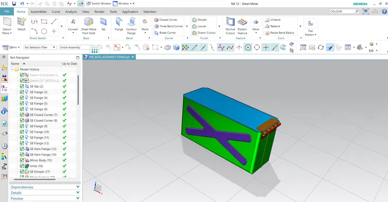
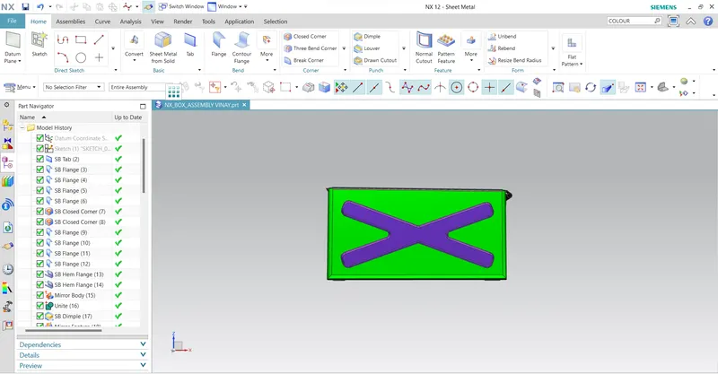
Create a dimple on the side of the box as shown in the diagram.
Create a dimple on the back side of the box.
Unbend and rebend the box assembly created.
Create the bead on the down surface of the box assembly and mirror it on the other side.
Create a hem surface on the flange.
Create a new plane at a 203mm at offset from z axis.
Sketch on the new surface and design the lid.
Create a flange on the newly created lid.
Sketch the tab and break the corner and create a flange and hem as shown in the figure with the dimension’s asper required.
Mirror the created part on the other side of the box.
Now create the tab on the upper side of the box and break corner of 10mm.
Create the flange and hem and cut the part using normal cut feature.
End the exercise.
Images of a Box Assembly:-
Isometric view:-
Front view:-
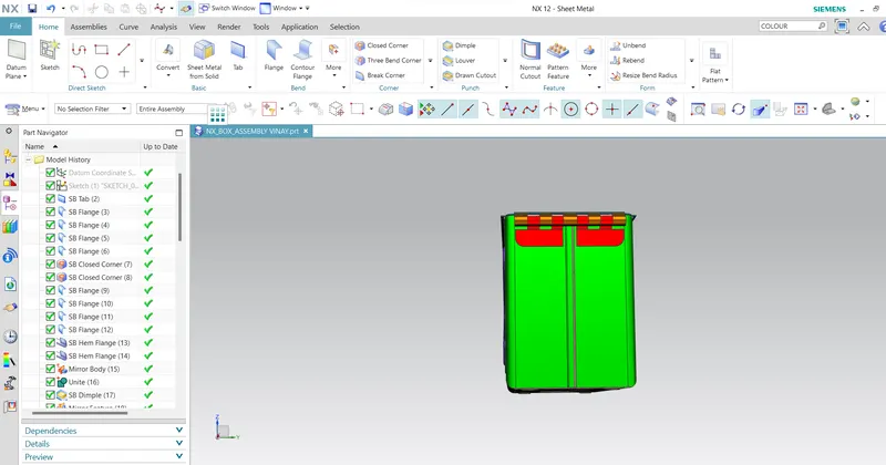
Side view:-
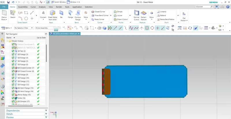
Top view:-
Conclusion:
At this created model of Box assembly is prepared.I have Learn creating tab, flange, bead, hole, dimple, and bend and rebend.