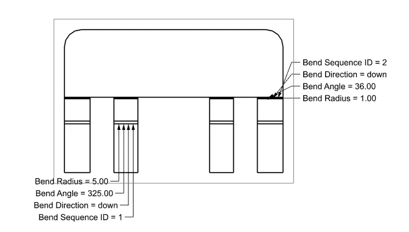
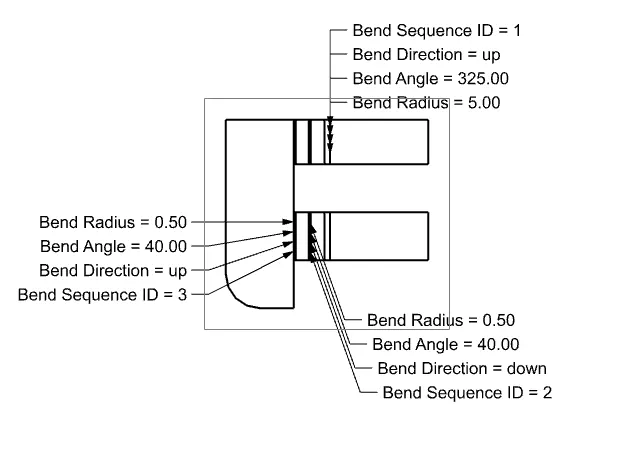
Advanced Sheet Metal Design Using NX Cad Challenge_2_Box Assembly
NX-Box Assembly
Aim:
To create Sheet Metal Component with Sheet Metal modelling tools applied throughout the modelling using NX.
Introduction:
In this we are going to create sheet metal Box Assembly step by step using seimens NX sheetmetal applicatiion.
Design methodology:
Tab -> Flange -> Closed corner -> Flange -> Hem Flange -> Mirror body -> Unite -> Dimple -> Mirror feature -> Dimple -> Bead -> Hem Flange -> Datum plane -> Flange -> Tab -> Flange -> Tab -> Flange -> Break corner -> Flange -> Hem Flange -> Unbend -> Normal cutout -> Rebend -> Mirror body -> Tab -> Break corner -> Flange -> Hem Flange -> Unbend -> Normal cutout -> Rebend.
Procedure:
Step 1: Tab
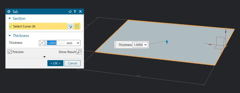
- Start Nx and create new file then the first step is to draw a sketch rectangle of length 200mm and width 150mm and exit sketch.
- Edit design parameter Menu -> parameters -> sheetmetal change the global value to 1mm and click ok.
- Then click tab button
 button for creating first sheet metal model.
Step 2: Flange
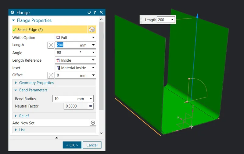
- Click the flange button
 use the length as 200 and select the outside edge as shown apply the same on the other side of the tab to obtain the final result as shown.
Step 3: Flange
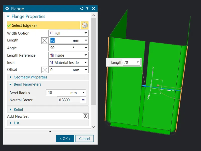
- Click the flange button use the length as 70mm and select the outside edge as shown apply the same on the other Flange to obtain the final result as shown.
Step 3: Closed Corner
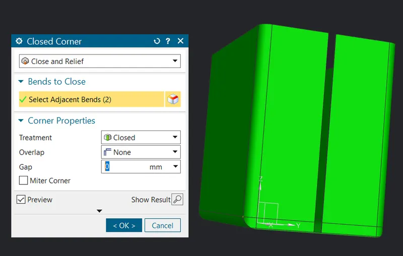
- Click on the closed corner button
 and select the edge to apply.
Step 4: Flange
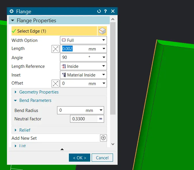
- Click the flange button use the length as 0.002 andbend radius as 0 select the inside edge as shown apply the same on the other Flange but this time select the outside edge to obtain the final result as shown.
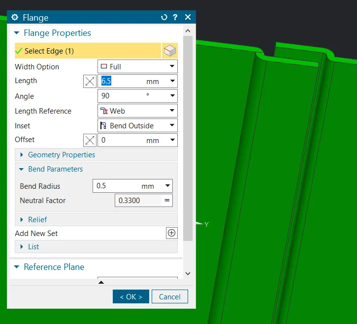
- Now select the flange button again and then again repeat the same procedure but on the previous flange with length of 6.5 and bend radius as 0.5.
Step 5: Hem Flange
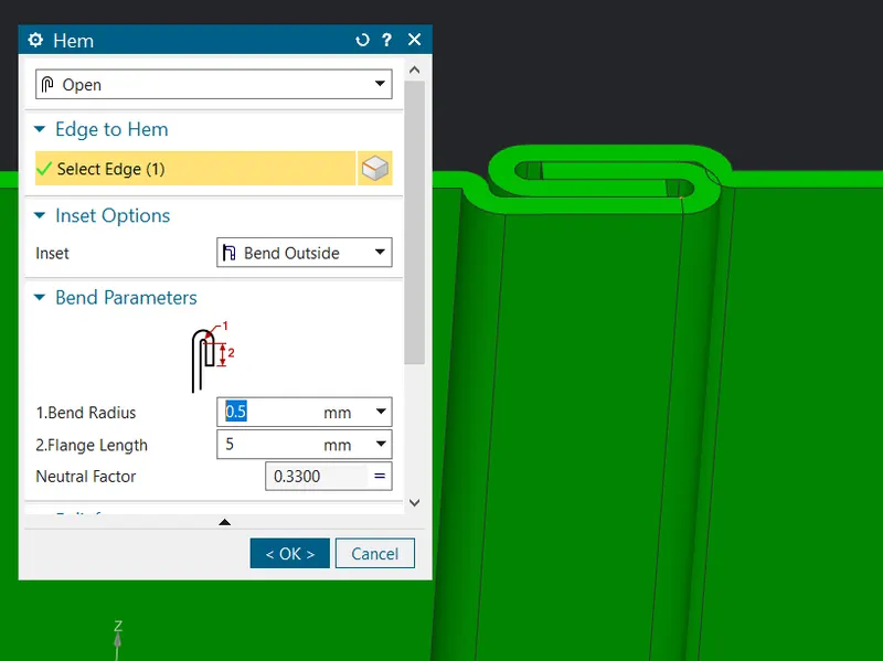
- Click the Hem flange button use the length as 5mm and select the outside edge as shown apply the same on the other Flange to obtain the final result as shown.
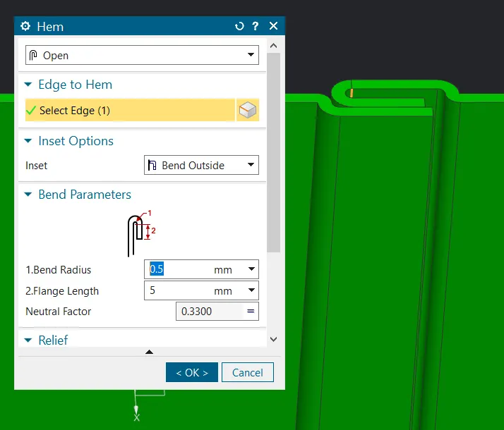
Do the same on other flange as shown.
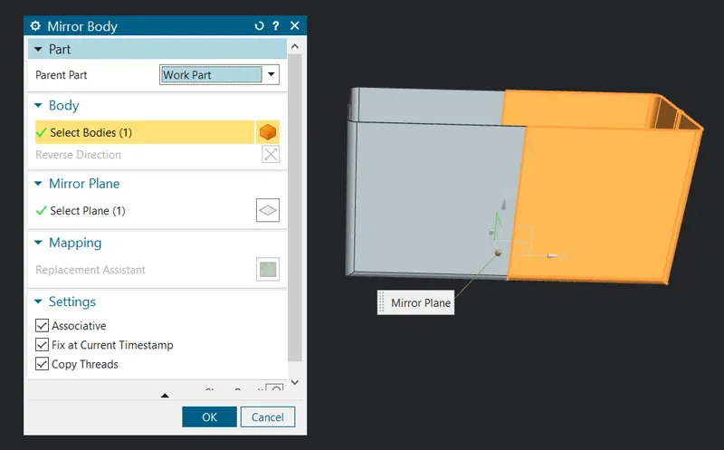
Step 6: Mirror body
- Now a half body is created so we need to mirror them to have a full box so use command finder to get mirror body feature then select the YZ plane as reference to mirror do as shown.
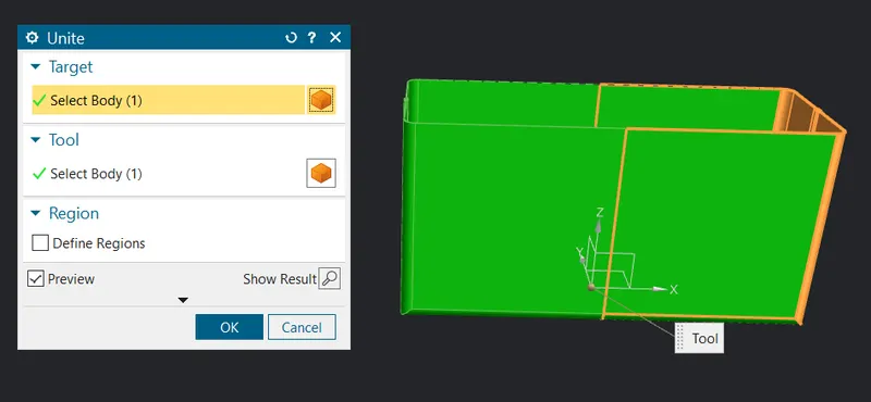
Step 7: Unite
- Eventhough we mirrored the body won't be a single unit so we are gonna make them to be by using the unite option
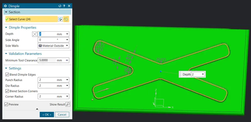
Step 8: Dimple
Then create a sketch and make a dimple
- Select the dimple button
 and give the value as shown.
.
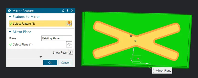
Step 9: Mirror feature
Its different from mirror body it simply mirror the feature so mirror the dimple on the other flange as well.
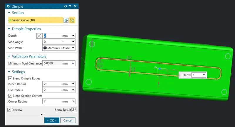
Step 10: Dimple
- Then create a sketch and make a dimple , Select the dimple button and give the value as shown.
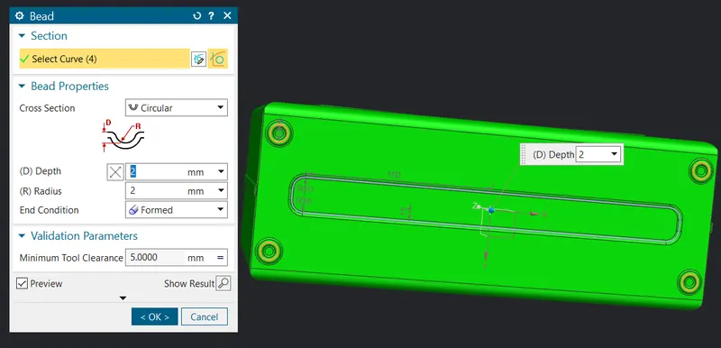
Step 11: Bead
- Click on the bead button from the more option in punch then sketch the circle and give the value as shown.
Step 12: Hem flange
Now use hem flange option to fold the edges of the box as shown.
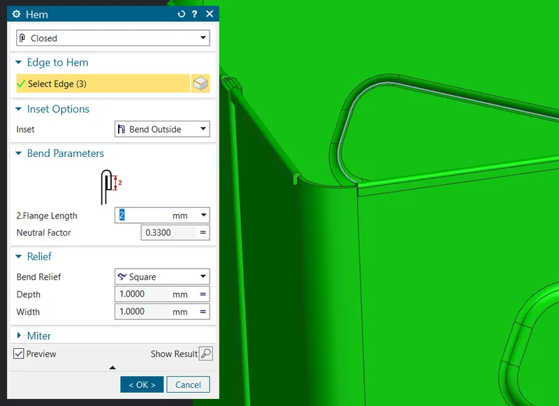
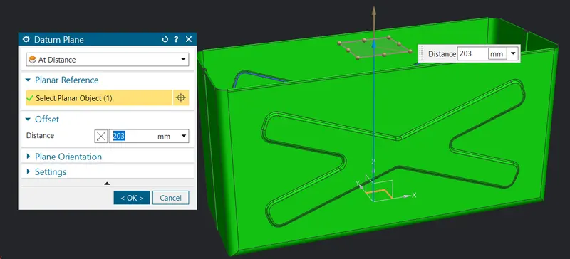
Step 13: Datum plane
To create a lid we need a plane on top to create a sketch and design them so click on datum plane option then do as shown.
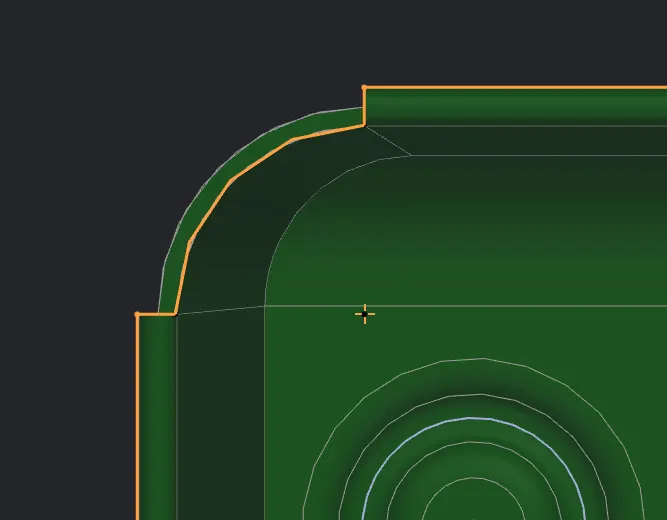
Step 14: Tab
First create a sketch on the datum plane as below.
Then use the tab option to create a lid.
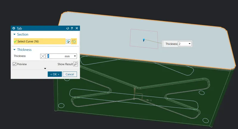
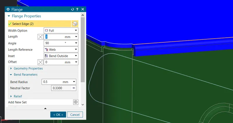
Step 15: Flange
- Click the flange button use the length as 3mm and select the outside edge as shown apply the same on the other side of the tab to obtain the final result as shown.
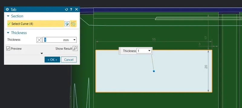
Step 16: Tab
Create a sketch and use them for tab option as ahown.
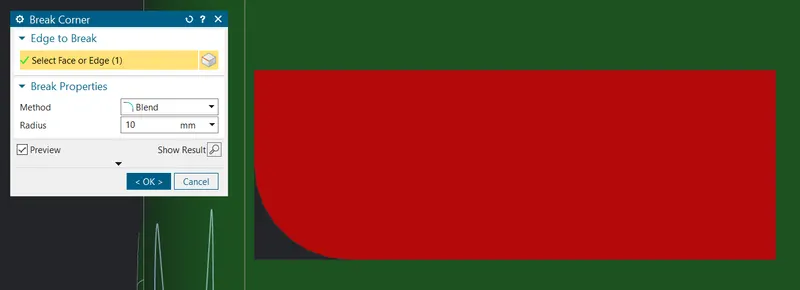
Step 17: Break corner
- Click on the break corner button
 and give the blend radius as 10mm the select the edge to apply.
Step 18: Flange
- Click the flange button use the length as 4mm & angle as 40 degree and select the outside edge as shown.
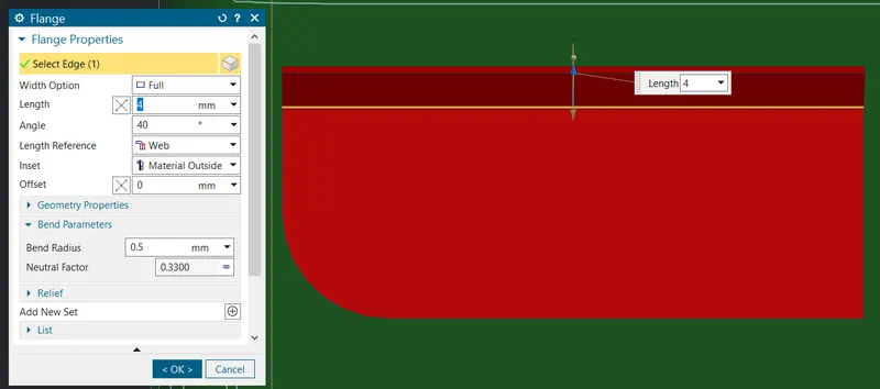
Do the same on the previous flange again.
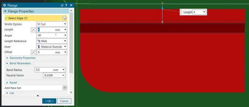
Step 19: Hem Flange
Now continue on the same flange but this time with hem flange as shown.
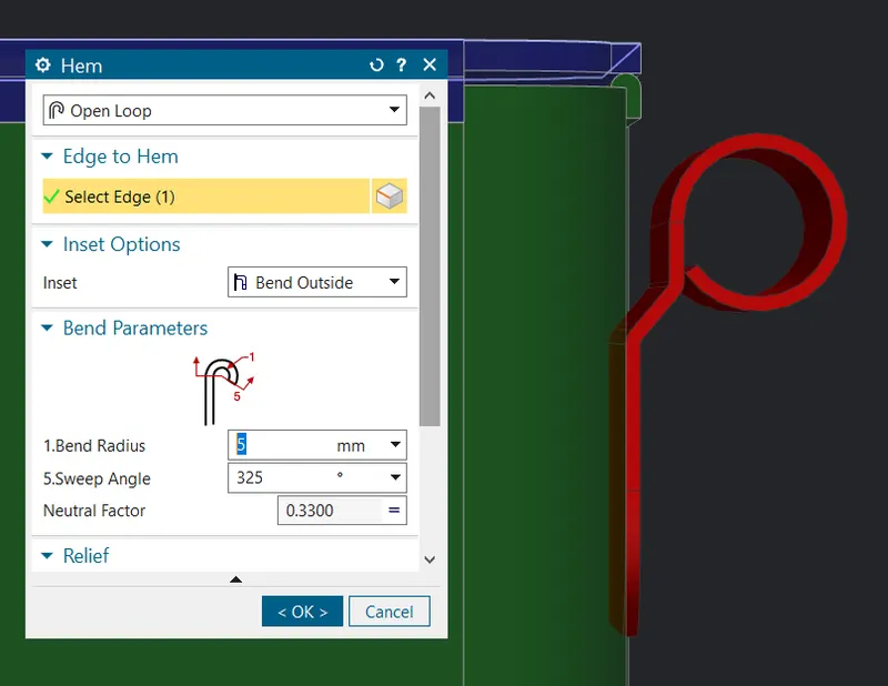
Step 20: Unbend
- Select the unbend button
 then give the stationary face as middle one and select the rest as bend.
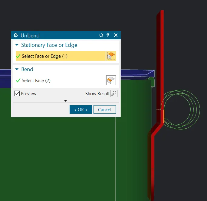
Step 21: Normal cutout
- Continue on the unbend flange with sketch as shown and use the cutout button
 for making a rectangular hole in the tab.
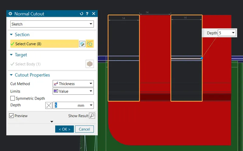
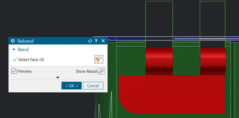
Step 22: Rebend
- Rebend the faces by selecting them in reverse order in which they were bend as shown.
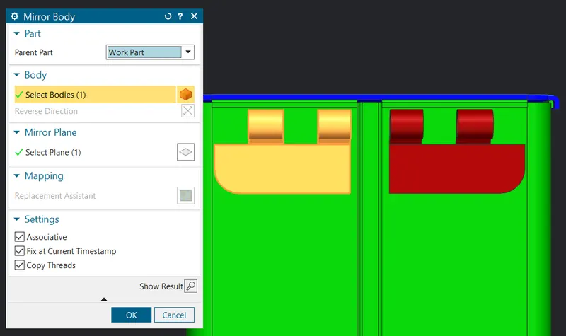
Step 23: Mirror body
- So use command finder to get mirror body feature then select the XZ plane as reference to mirror do as shown.
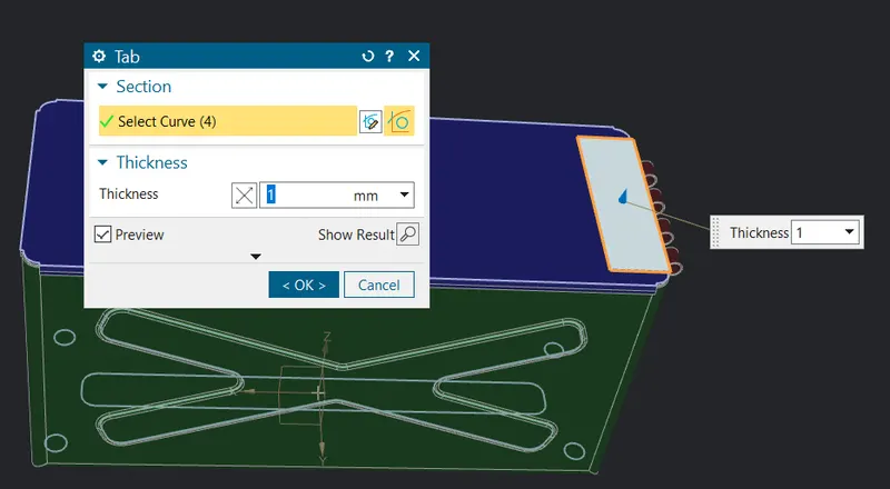
Step 24: Tab
Create a tab as shown below on the lid for hinges.
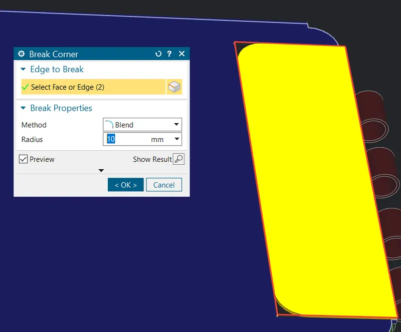
Step 25: Break corner
- Click on the break corner button and give the blend radius as 10mm the select the edge or face to apply.
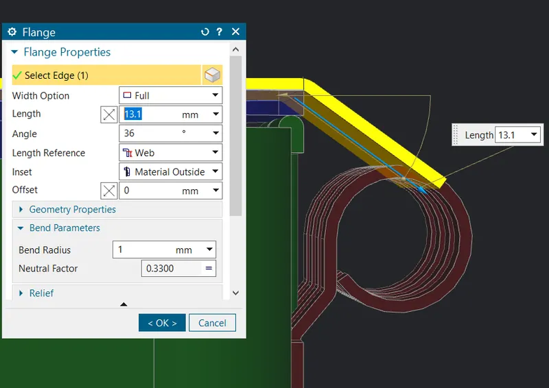
Step 26: Flange
- Click the flange button use the length as 13.1mm & angle as 36 degree and select the outside edge as shown.
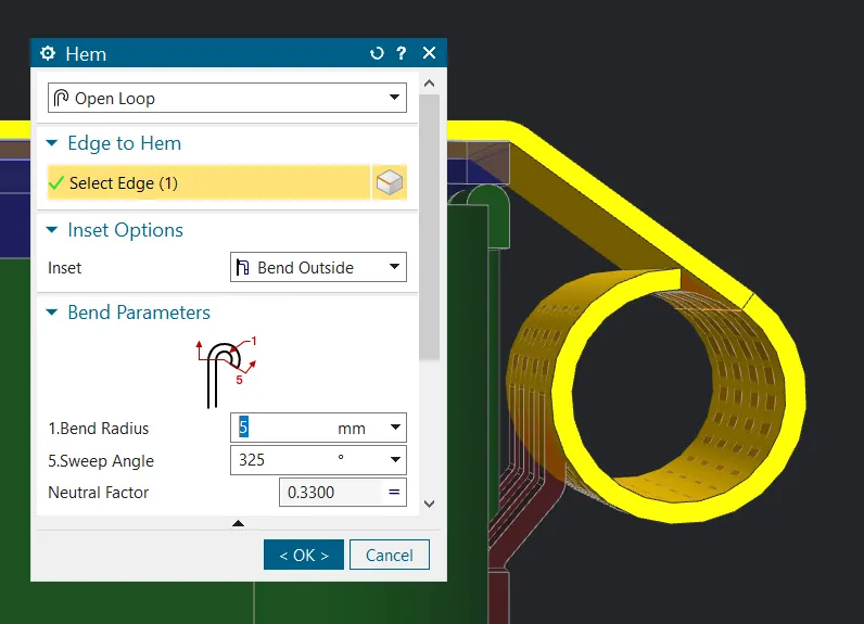
Step 27: Hem Flange
Now continue on the same flange but this time with hem flange as shown.
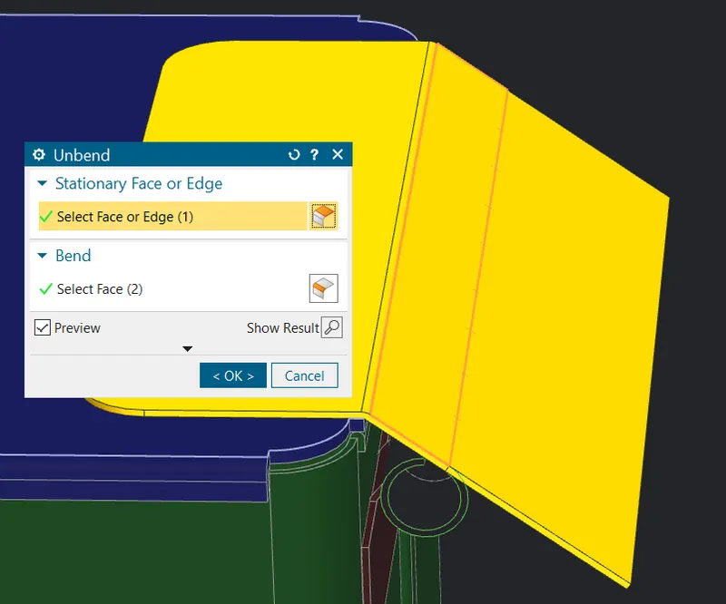
Step 28: Unbend
- Select the unbend button then give the stationary face as middle one and select the rest as bend.
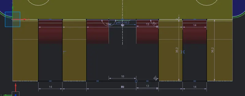
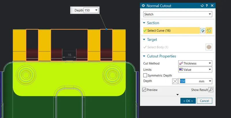
Step 29: Normal cutout
- Continue on the unbend flange with sketch as shown and use the cutout button for making a rectangular hole in the tab.
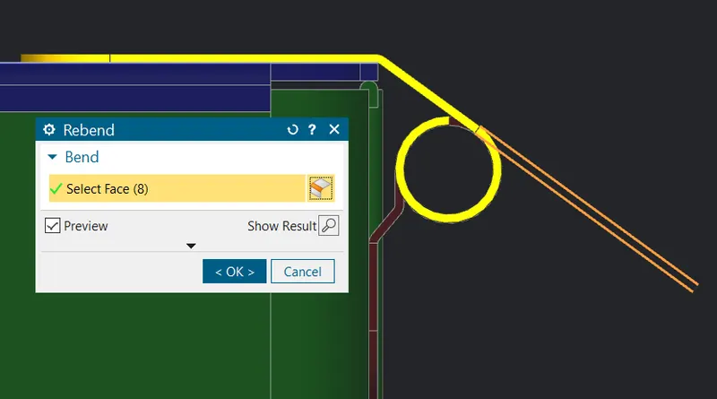
Step 30: Rebend
- Rebend the faces by selecting them in reverse order in which they were bend as shown.
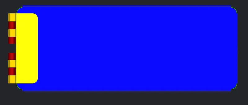
Result:
Top view
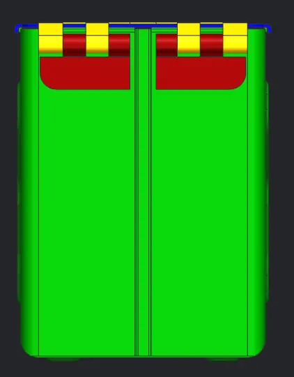
Left side view
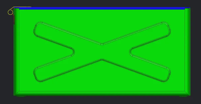
Front side view
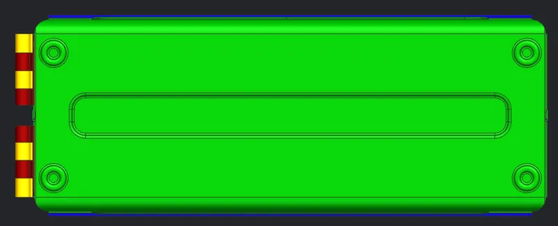
Bottom side view
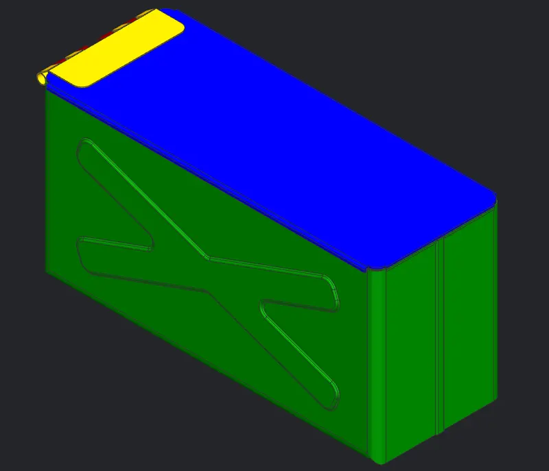
Isometric view
Drafting:
Box
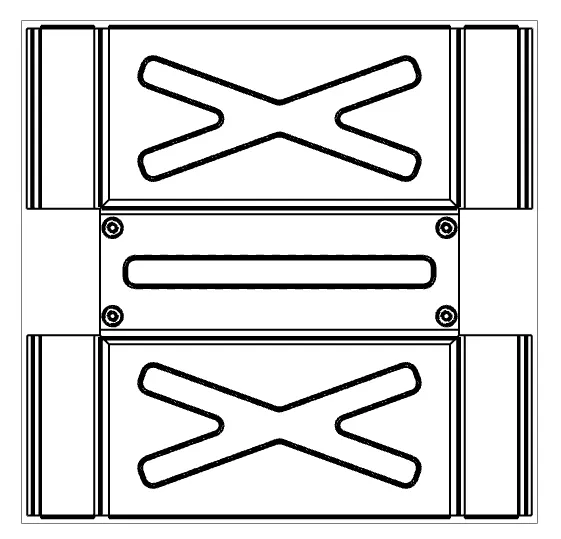
Lid
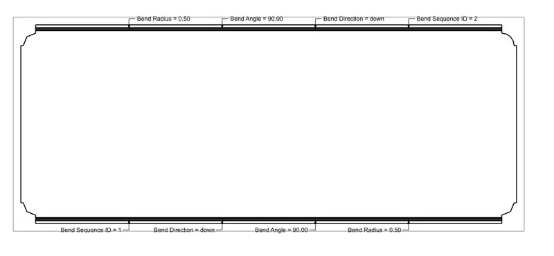
Hinges