Advanced Sheet Metal Design Using NX Cad Challenge_2_Box Assembly
Aim: Advanced Sheet Metal Design Using NX Cad Challenge_2_Box Assembly
Objective: Write a detailed report on Sheet Metal Component with good explanation on Sheet Metal modelling tools applied throughout the modelling. Also attach the Final model Images (Min. 4 images) of Sheet Metal Box Assembly.
Link for PDF.
https://drive.google.com/open?id=1kjkKrjCXfoGbNzqP9lZ9ogPpNIswBoLR
Points to be followed in report
- Title of the Project
- Objective
- Introduction
- Design methodology / approach (To be explained with the help of Flowcharts only)
- Description (Need to explain tools/ Features used while designing)
- Upload a min of four screenshots of Model in the report. (Front View, Side View, Isometric View and the Top View)
- Attach Detailed Drawing Sheet Image (If Required)
- Conclusion
Title of the Project : Advanced Sheet Metal Design Using NX Cad Challenge_2_Box Assembly
Objective : To design a 'Box Assembly' using Siemens NX Sheetmetal Application
Introduction :
Sheet metal is metal formed by an industrial process into thin, flat pieces. Sheet metal is one of the fundamental forms used in metal working and it can be cut and bent into a variety of shapes. Countless everyday objects are fabricated from sheet metal.A sheet metal Box Assembly was selected for this project to understand the basics of Sheet metal application in Siemens NX. The box assembly has some important features like flange, dimple, normal cutouts etc. The box assembly is a basic component which can be used as a CPU cover and other electronic components etc.
Sheet metal is any metal that has a thickness in between 0.5 mm and 6 mm. Any metal piece thicker than 6mm are considered as Structural Metal (for ex. Structural Steel) and any metal piece having thickness lower than 0.2mm is called Metal Foil (for ex. Aluminum Foil).NX, formerly known as "unigraphics", is an advanced high-end CAD/CAM/CAE, which has been owned since 2007 by Siemens PLM Software. In 2000, Unigraphics purchased SDRC I-DEAS and began an effort to integrate aspects of both software packages into a single product which became Unigraphics NX or NX.
Design methodology / approach (To be explained with the help of Flowcharts only)
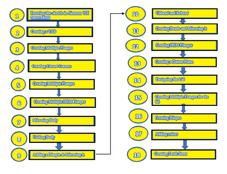
Description :
Sketch: It is basic comand to draw to draw 2d models 200mm in X direction and 150mm width along Y direction.
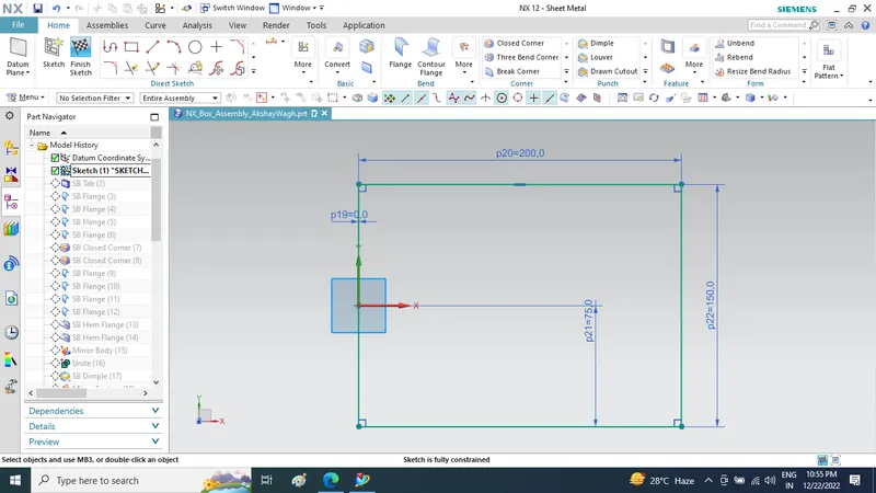
Tab: This command is used to create a base feature by extruding a sketch along vector by a thickness value or by adding material to exixting faces and bend regions of sheetmetal part.
- This will create a Tab of 1mm thickness.

CREATING MULTIPLE FLANGES:: This command is used to add a flat flange at a angle to the planar faceand add a bend between the two. A flange consists of bend region and a web.
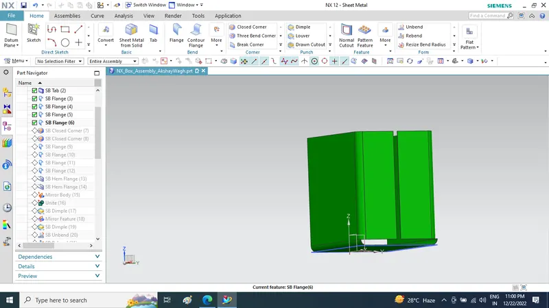
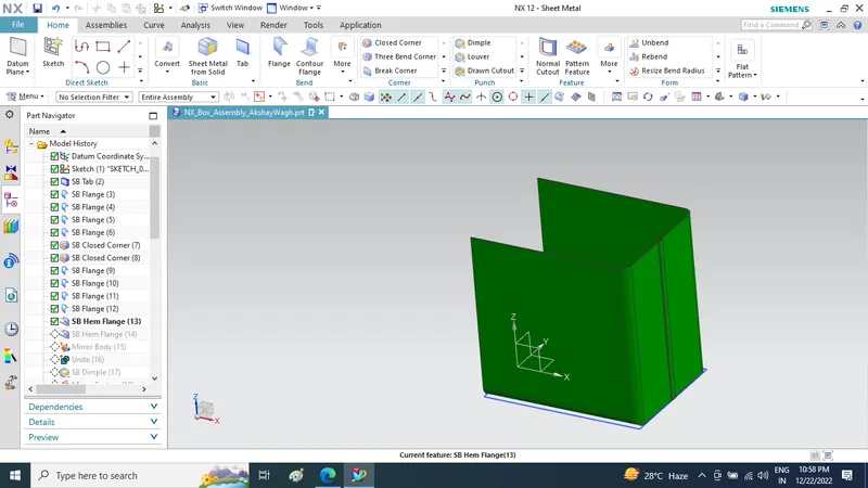
CREATING CLOSED CORNERS: This command is used to modify two flanges in one operation and to close the corner where the two flanges meet.
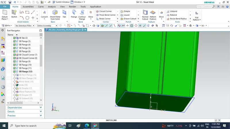
CREATING MULTIPLE FLANGES :is command is used to add a flat flange at a angle to the planar faceand add a bend between the two. A flange consists of bend region and a web.
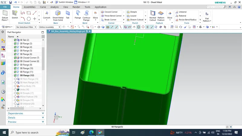
Hem Flange: This command is used to modify an edgeof a sheetmetal part by folding it on to itself for the purpose odf safe handling or to increase edge stiffness.
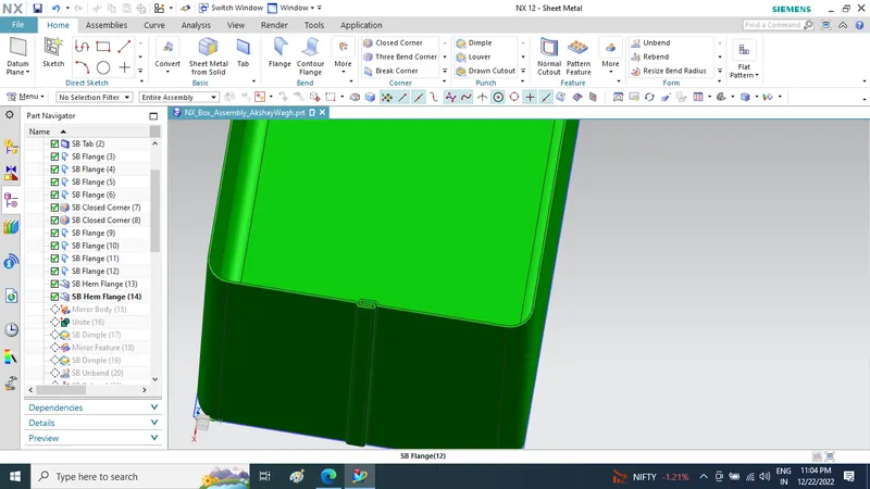
Mirror Body: This command is used to mirror the part w.r.t the required axis.
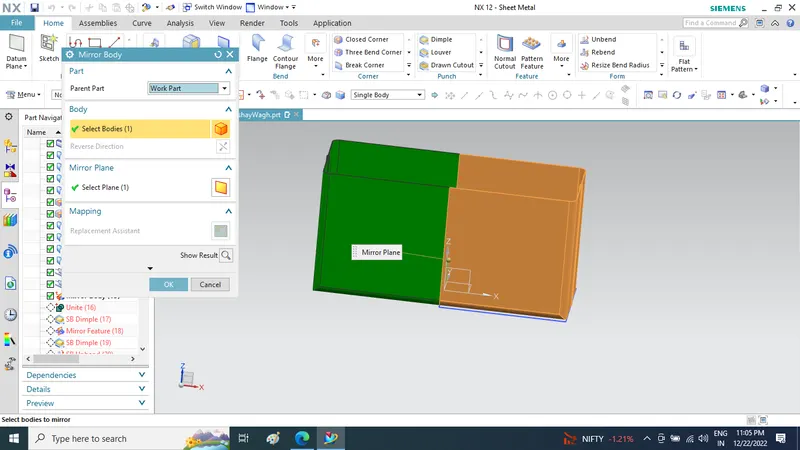
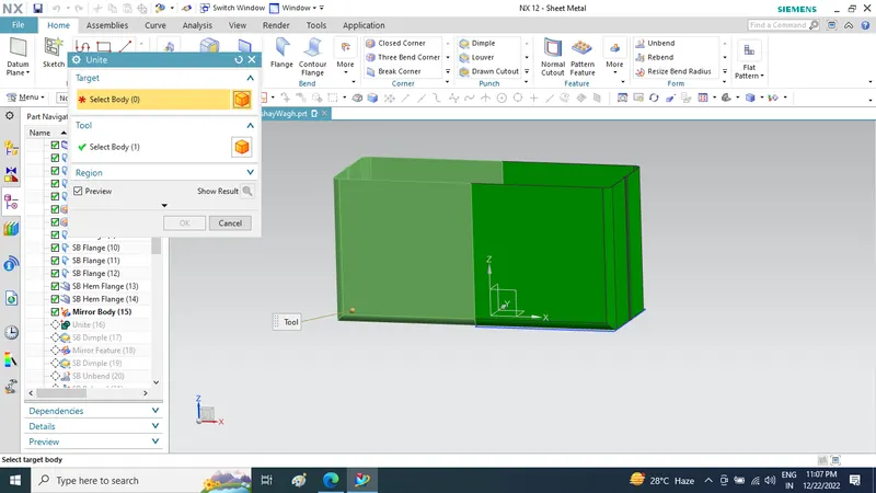
Unite: This command is used to combine the two parts into one part.
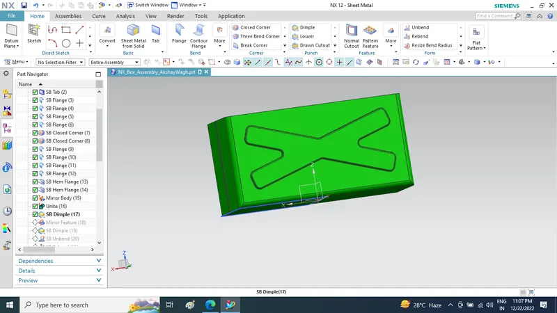
Dimple: This command is used to lift an area of the model inside the sketch that stimulates a stamping tool.
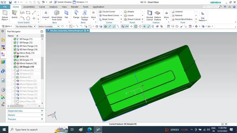
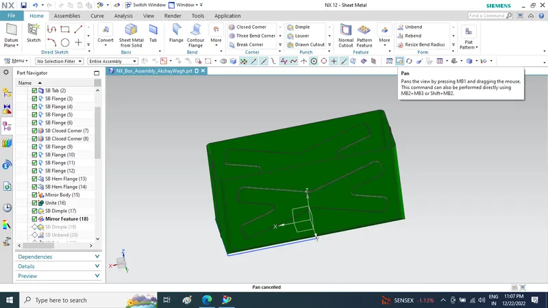
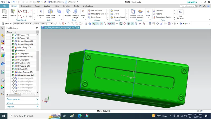
Mirror Feature: This command is used to mirror the required sketch to other side with reference to the axis.
Unbend: This command is used to faltten the 3D model by selecting one stationary face.
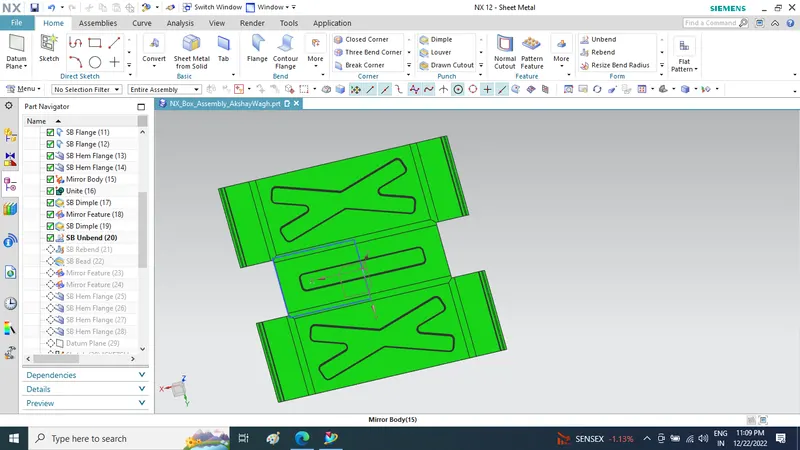
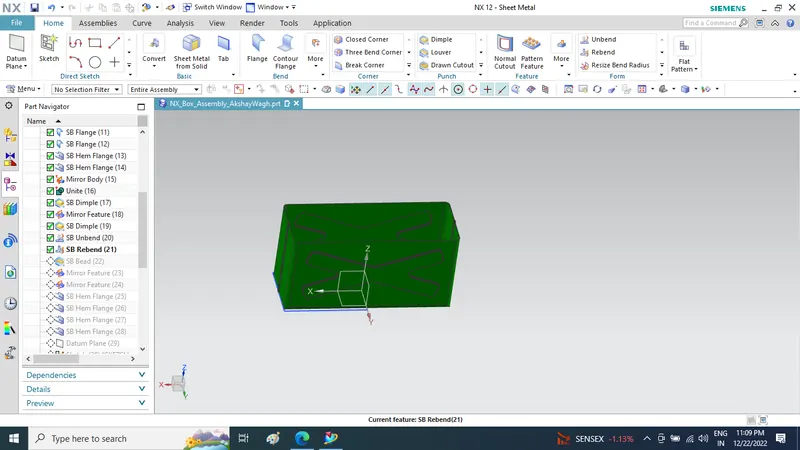
Rebend: This command is used to rebend the flattern sheet material.
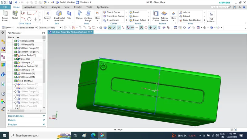
Bead: This command is used to lift material along contour of a sketch that stimulates a stamping tool. Bead can also be created to stiffen sheet material. and mirror feature it
Multiple Hem Flange: This command is used to modify an edgeof a sheetmetal part by folding it on to itself for the purpose odf safe handling or to increase edge stiffness.
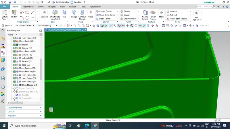
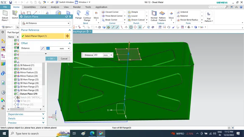
Datum Plane: This feature is used to project the plane at a certain distance 203 by giving the distance.
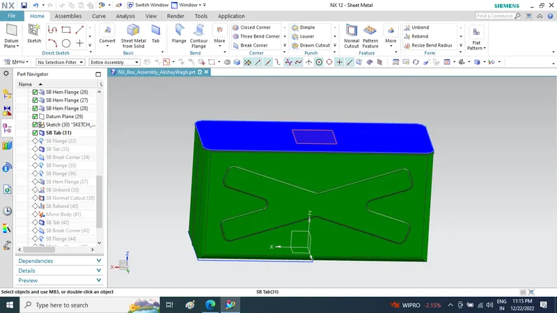
DESIGNING THE LID & CREATING MULTIPLE FLANGES for Lid: Create a new sketch on the newly created plane by clicking on the sketch button and then selecting the new plane thus created Create a Tab after closing all the gaps in the sketch.
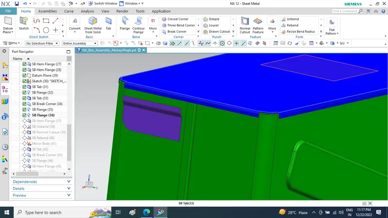
CREATING MULTIPLE FLANGES :Create Multiple Flanges at 90 degrees along the outer edges of the lid by clicking on the ‘Flange’ button & Use Break Corner This command is used to round or chamfer sharp corners of a tab or flange.
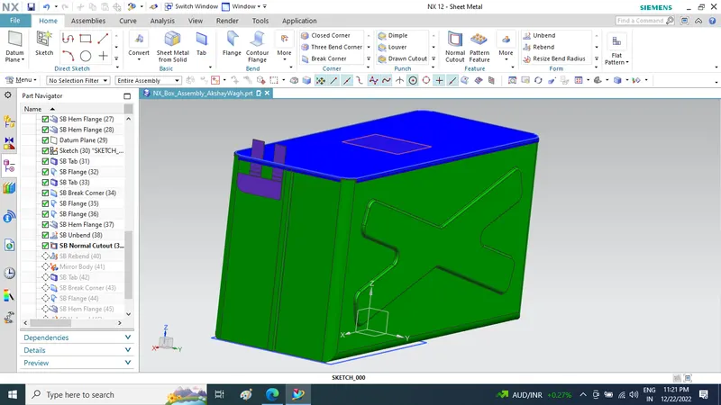
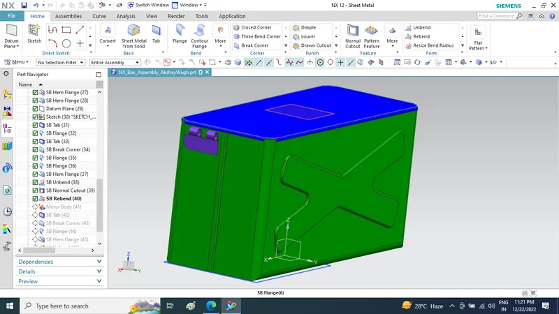
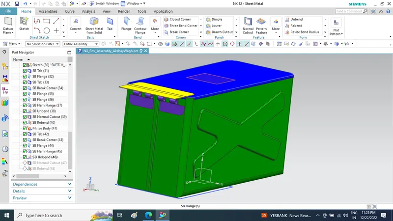
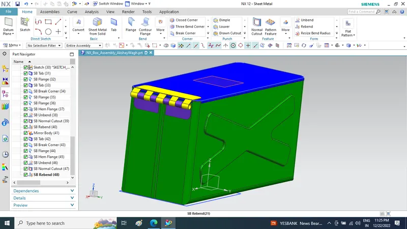
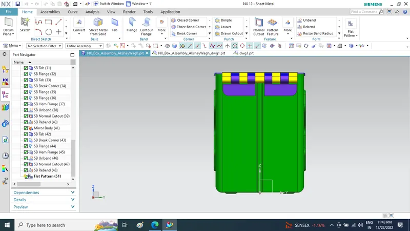
CREATING HINGES : Create a sketch on the left side face of the box assembly by clicking on the sketch button and selecting the left side face.Create a hem flange – Type as open type – select the outer edge of the flange created in the previous step – inset as bend outside – bend radius as 5mm – sweep angle as 325degree – leave Neutral Factor as it is Create a sketch on the unbend section – Draw four Rectangles located at a similar distance from each other – Exit the sketch – click on normal cutout – select the type as Sketch – Cut method as thickness – Limits as value – Depth as 5mm – click on ok. Rebend again all the flanges and hem flanges. Create a mirror body for the part thus created.
ADDING COLORS:
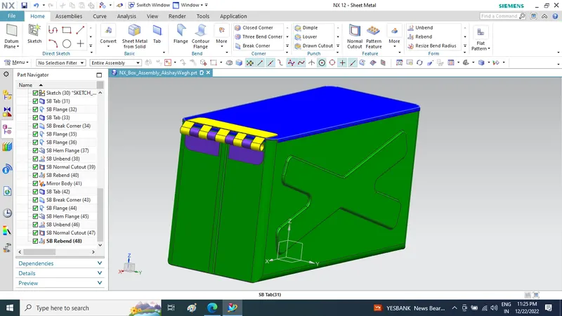
CREATING DRAFT SHEET
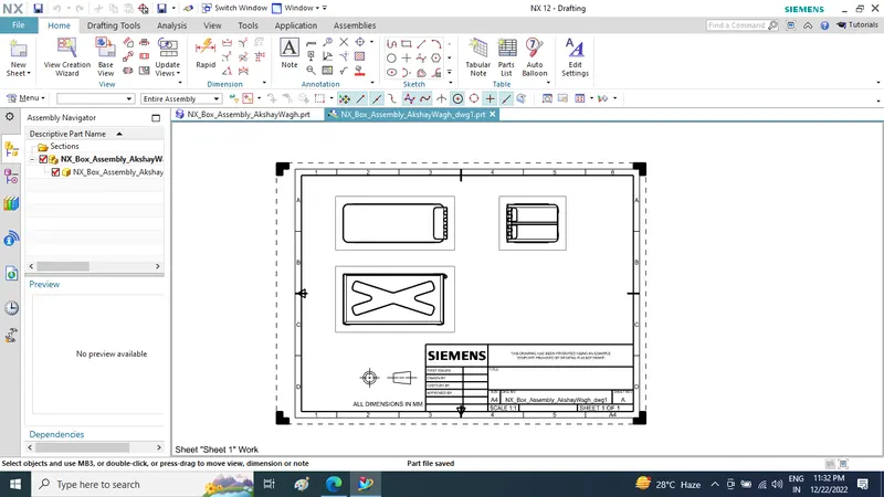
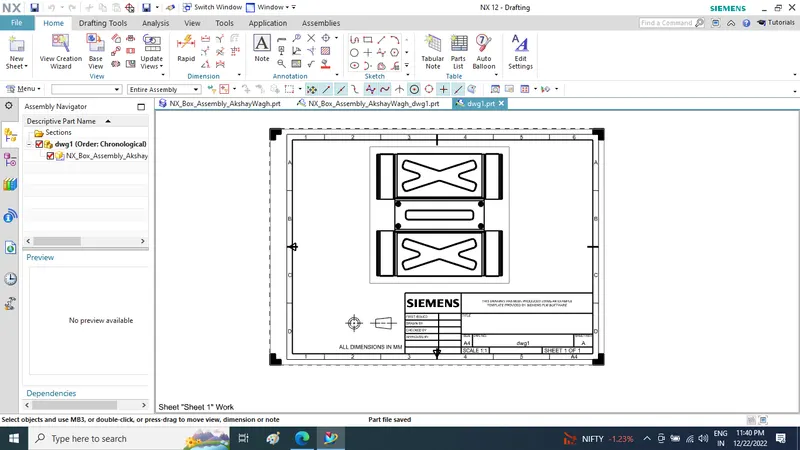
Images of a Box Assembly:
Isometric view
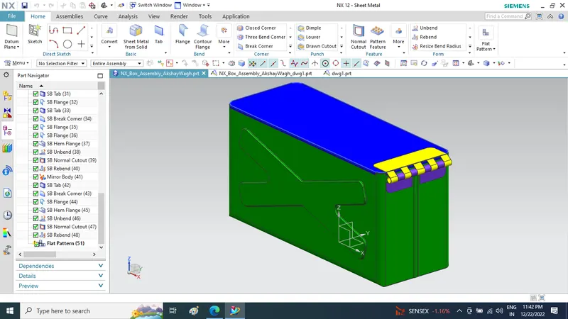
Front view
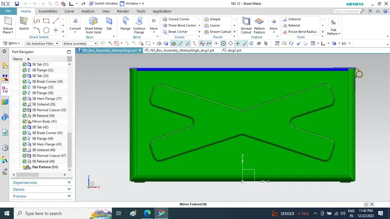
Side view
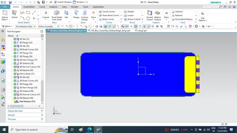
Top view
CAD File is in zip folder attched with Report Plz Find it
Conclusion:
The project has been completed by designing a sheet metal, Box Assembly has been designed by using Siemens NX Sheet Metal and learnt about the various features and options had been executed successfully.