Advanced Sheet Metal Design Using NX Cad Challenge_2_Box Assembly
SHEET METAL MODELLING OF A BOX ASSEMBLY DESIGN
Objective
The main objective of this project is to design a sheet metal casing in the NX cad sheet metal application workbench. Also, to perform the drafting for the BOX ASSEMBLY part.
Software used: NX 12.0
-
To design and model the sheet metal Box assembly in NX by using some basic features.
-
To learn to create sketches on defined planes as per requirement.
-
To master the user interface and basic features of Sheet metal application in NX like Tab, Flange, Break corner, Unbend, Creating holes, Re-bend, Dimple, Bead, cutout, Mirror feature, and Flat pattern etc
Introduction
Sheet Metal Design
Sheet Metal Fabrication is the process of forming parts from a metal sheet by punching, cutting, stamping, and bending. 3D CAD files are converted into machine code, which controls a machine to precisely cut and form the sheets into the final part.
3D CAD files are converted into machine code, which controls a machine to precisely cut and form the sheets into the final part.
Sheet metal parts are known for their durability, which makes them great for end use applications (e.g. chassis). Parts used for low volume prototypes, and high volume production runs are most cost-effective due to large initial setup and material costs.
Because parts are formed from a single sheet of metal, designs must maintain a uniform thickness. Be sure to follow the design requirements and tolerances to ensure parts fall closer to design intent and cutting sheets of metal
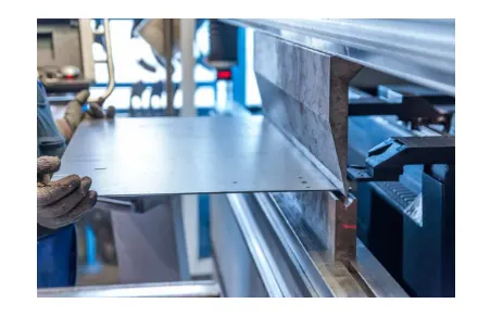
Sheet metal is any metal that has a thickness in between 0.5 mm and 6 mm. Any metal piece thicker than 6mm are considered as Structural Metal (for ex. Structural Steel) and any metal piece having thickness lower than 0.2mm is called Metal Foil (for ex. Aluminum Foil).
Sheet metal is one of the fundamental forms used in metalworking, and it can be cut and bent into a variety of shapes. It is found in various industrial application ranging from small and light Fixture to an Automotive Body Part. Sheet metal applications have wide range due to its properties like: High Strength, Low weight and Corrosion Resistance.
General Sheet Metal materials are Steel, Aluminum, Brass, Titanium. There are 2 ways of producing Sheet Metal – Hot Rolling and Cold Rolling. For precision applications, cold rolled steels are preferred as manufacturers have more control over the final dimensions. This is because in hot rolled steels, after cooling, the steel shrinks slightly and the shape might change a little.
Critical Dimensions
The following are some terminology that are used in sheet metal. Designers need to adhere to machinery guidelines when designing for bending. Bends can be characterised by these parameters. Some critical dimensions that need to be considered when setting up sheet metal in CAD software are sheet metal thickness, the k-factor and bend radius. One needs to check that these factors are consistent with the tooling that will be used in manufacturing. This guide gives important guidelines for good design practice
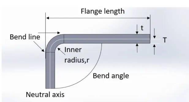
Bend line– The straight line on the surface of the sheet, on either side of the bend, that defines the end of the level flange and the start of the bend.
Bend radius – The distance from the bend axis to the inside surface of the material, between the bend lines.
Bend angle – The angle of the bend, measured between the bent flange and its original position, or as the included angle between perpendicular lines drawn from the bend lines.Sometimes specified as the inside bend radius. The outside bend radius is equal to the inside bend radius plus the sheet thickness.
Neutral axis – The location in the sheet that is neither stretched nor compressed, and therefore remains at a constant length.
K-factor – The location of the neutral axis in the material, calculated as the ratio of the distance of the neutral axis T, to the material thickness t. The K-factor is dependent upon several factors (material, bending operation, bend angle, etc.) and is greater than 0.25, but cannot exceed 0.50. K factor = T/t
Bend allowance – The length of the neutral axis between the bend lines or the arc length of the bend. The bend allowance added to the flange lengths is equal to the total flat length.
Introduction about project
Sheet metal is a metal forming process through the industrial process into thin, flat pieces. Here, I have created a Sheet Metal Box assembly of Various thickened parts. Box assembly contains 3 main parts.
1. Box (base part)
2. Box Lid
3. Hinge
To design this parts I have used NX sheet metal workbench. The design methodology I have used to design this is described below.
Design Methodology
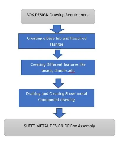
The sheet metal Box assembly has been done with the above flow chart process. While designing the default thickness, bend radius relief depth and relief width value are set to 1mm at the Menu → Preferences → Sheet Metal here you can change the Sheet Metal thickness whenever necessary.
The sketch is drawn in the XY plane and the tab command is used for creating the base of the part.
Explanation and Procedure:
1.Direct Sketch: We use its tools to create a base sketch. (for eg: Rectangle, Circle, Line, etc.)
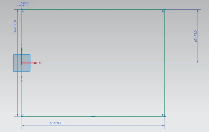
2.Tab: This tool act as an extrude (i.e) 2D sketch to 3D sketch can be done.
Tab Creation:
-
XY Plane - Create a sketch by drawing a symmetric rectangle wrt an X axis at the origin. Exit the sketch mode.
-
Change the design Parameters as per requirement.
-
Use Tab feature to create a rectangular metal sheet.
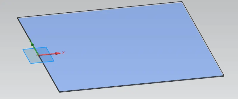
3.Flange: Adds a flat flange at an angle to a planar face and adds a bend between the two.
Flange Creation:
-
Use Flange Feature and select appropriate edges to create flanges normal to XY & XZ Plane respectively.
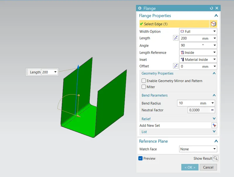
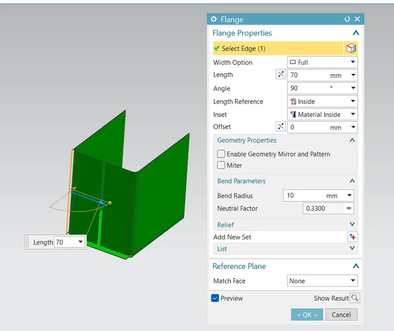
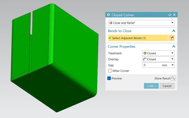
4.Closed Corner Closes a corner where two adjacent flanges meet by extending the bends and flanges.
Closed Corners creation
-
Use Closed Corner and select bends of adjacent flanges to close the corners.
5.Flange Creation:
-
Use Flange Feature and select the edge of previously created flange.
-
Create one more flange using above flange edge.
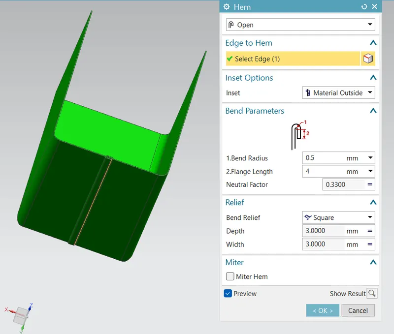
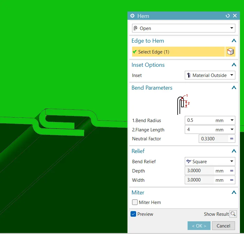
6.Hem Flange Creation:
1.Create an open type Hem flange by selecting edge of flange created in step 5
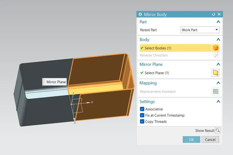
7.Mirror body: This command is used to mirror the body created with respect to the plane selection.
Mirror Body creation:
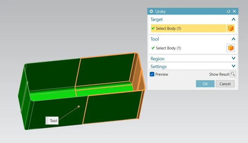
8.Unite: Combines the volume of two or more solid bodies into a single body.
Unite creation:
-
Use the two bodies (Created & mirror body) to unite.
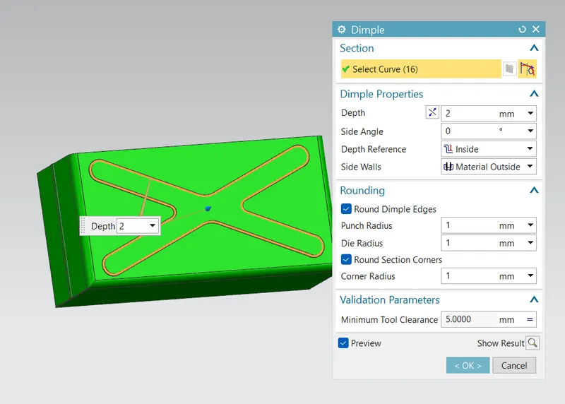
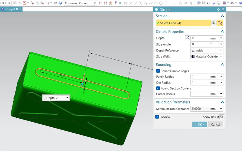
9.Dimple: The dimple feature can be placed on any flat face including flanges and will extend in the direction of the face. Dimple dies are designed to reduce the weight in sheet metal fabrications, while adding strength and rigidity.
Dimple Creation (Side face):
-
Select the Side face of the Box and Create a sketch in the shape of "X". Apply sketch fillets to the edges to round the corners and connecting edges.
-
Use Dimple feature to create a stamp on it.
Dimple Creation (Bottom face):
-
Select the Bottom face of the Box and Create a sketch using rectangle. Apply sketch fillets to the edges to round the corners.
-
Use Dimple feature to create a stamp on it.
10.Bead:
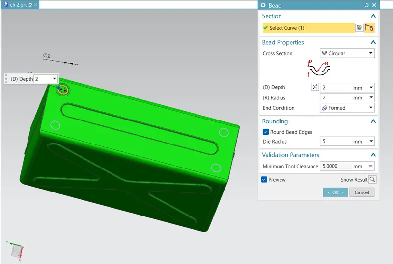
A Bead is a long, drawn out impression, which is impressed to increase stiffness in metal sheets or plates. It is also important that how the bead runs over the work piece.
Bead Creation (Bottom face):
-
Select the Bottom face of the Box and Create a sketch using Circle.
-
Use Bead feature to create a stamp on it.
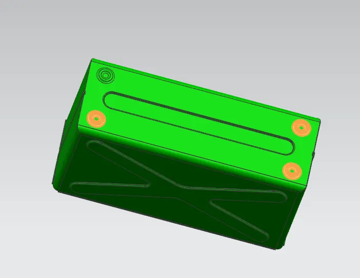
Create point for other Bead using mirror command
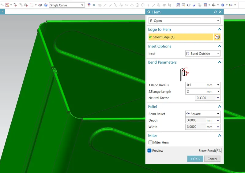
11.Hem Flange: Modifies the model by folding the edge of sheet metal flange over onto itself for the purpose of safe handling or to increase edge stiffness.
Hem Flange Creation (Top face):
-
Select the top edges and use Closed type Hem flange to fold the Material
12.Box Cover (TOP)
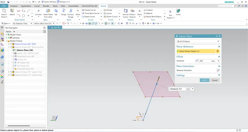
Datum Plane: Creates a datum plane used to construct Box Cover by Sketch (Top) features.
Box Top Face
-
Create a Datum plane at an offset of 203mm from bottom face.
-
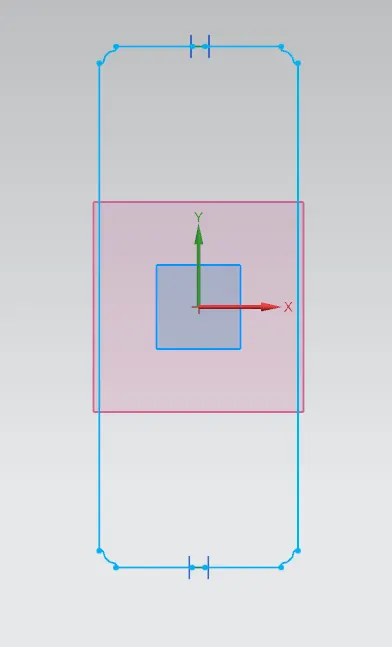
Now sketch on newly created plane using projection courve in such a way that it forms box shape.
-
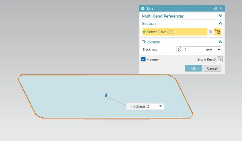
Use Tab feature and select the sketch to create top face
-
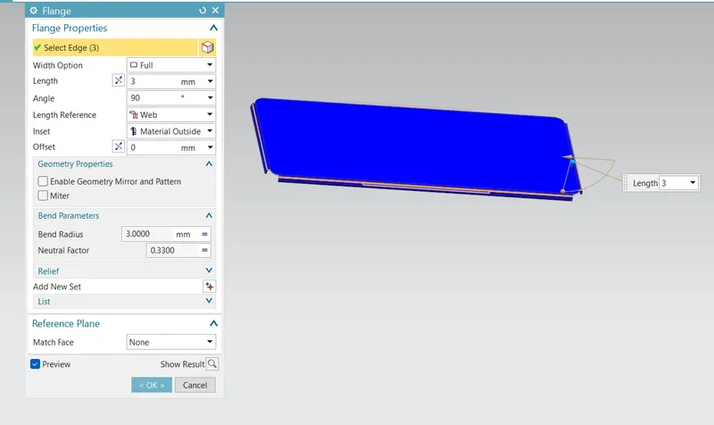
Extend the edges of lid by using Flange feature
Tab the close surface by 2 mm
giving the 3 mm flange to outer edge
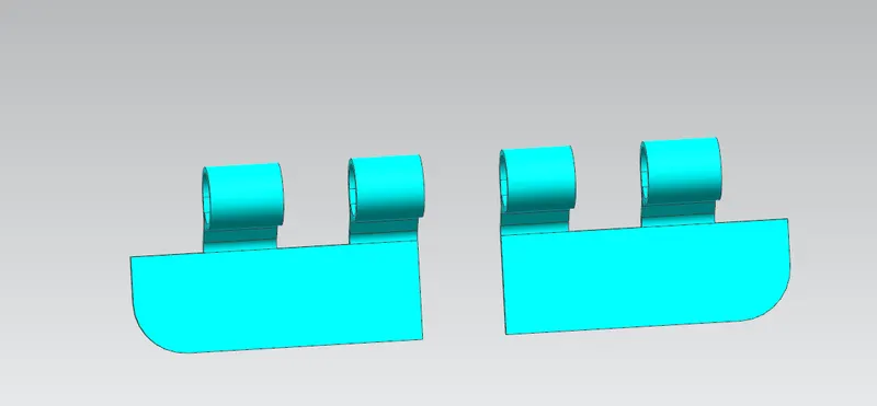
13.Hinge Creation (Lower Hinge ):
-
Create a Sketch on side face by drawing a rectangle. Exit the Sketch.
-
Create a Tab by selecting above sketch.
-
Use Break corners and select the bottom left edge to round it.
-
Create a flange at an angle by selecting edge of previously extruded Tab.
-
Now use Open loop type Hem. flange by selecting proper edge to create a fold.
-
Unbend the fold and created a sketch by drawing few rectangle. Exit the Sketch and do Normal cutout.
-
Re-bend the fold.
-
Mirror the Hinge about XZ Plane.
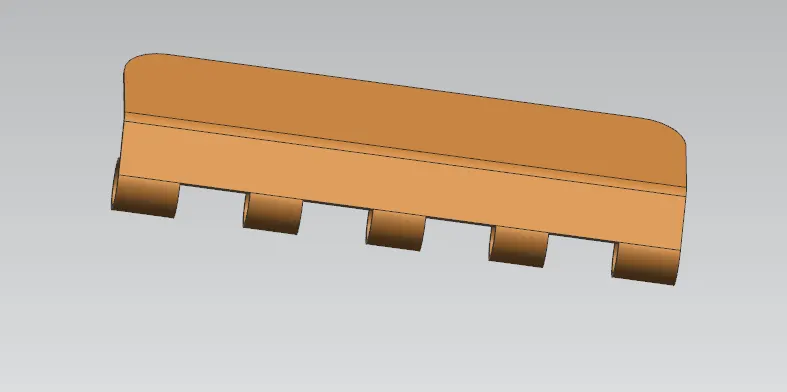
14.Hinge Creation (Upper Hinge):
-
Create a Sketch on top face by drawing a rectangle. Exit the Sketch.
-
Create a Tab by selecting above sketch.
-
Use Break corners and select the top left & right edges to round it.
-
Create a flange at an angle by selecting edge of previously extruded Tab.
-
Now use Open loop type Hem. flange by selecting proper edge to create a fold.
-
Unbend the fold and created a sketch by drawing few rectangle. Exit the Sketch and do Normal cutout.
-
Re-bend the fold.
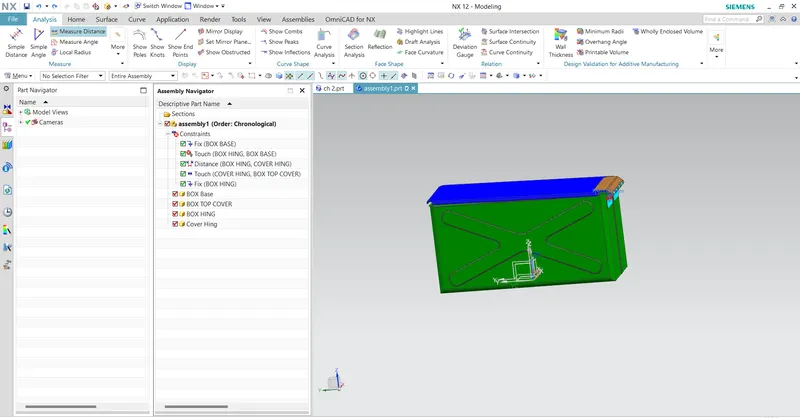
15.Assembly of BOX
1.create new file for assembly
2.Adding all part model into assembly file
3.providing fix constrain to the box
4.after using assembly constrain assemble all 4 part to each other
16.Drafting:
We can create 2D drawing sheets in NX CAD from the sheet metal component designed. For that we have to follow the process below:
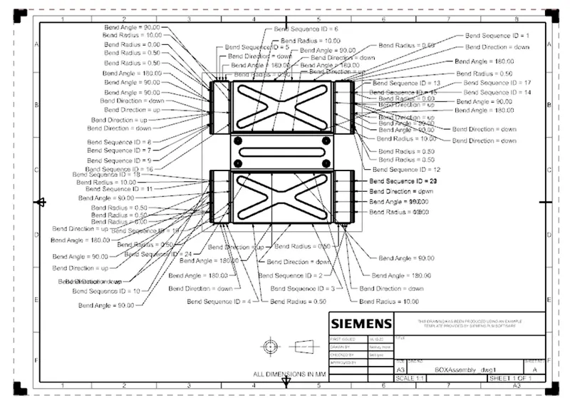
Application >> Drafting >> Base View >> In model view to use - FLAT PATTERN created >> Adjust appropriate scale >> Drawing Sheet formed >> Give Proper Dimensions.
Drawing sheet:
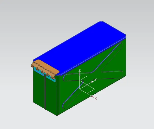
17.Drawing view
1.Isometric View
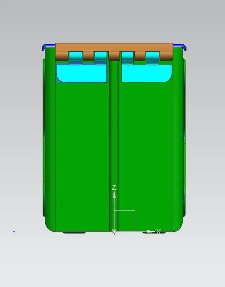
2.Front View
3.Side View
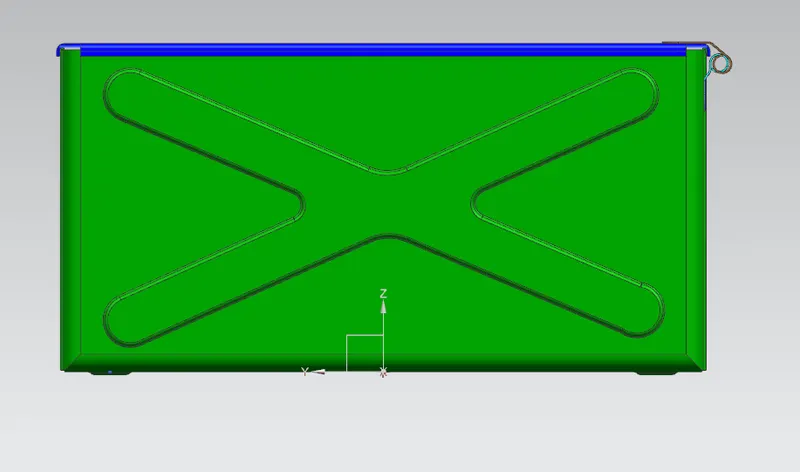
4.Top View
CONCLUSION:
-
Finally, the box assembly of the sheet metal is designed on the Siemens NX12.0
-
The tools and features used for the box assembly are learned.