Design Box Assembly
Objective:- The objective of this challenge is to design a Box Assembly by using Siemens NX Sheet metal Application and try to understand the tools used in this challenge.
Introduction:-
Sheet metal is metal formed by an industrial process into thin, flat pieces. Sheet metal is one of the fundamental forms used in metal working and it can be cut and bent into a variety of shapes. Countless everyday objects are fabricated from sheet metal.
NX cad is a designing software that is primarily concerned with the sheet metal designing. The tools and features available are unlike other softwares such as SOLID-WORKS or CREO. The tools are specific enough to make sheet metal designing easier. Given the fact that manufacturing a proper component is key in the mechanical industry also the fact that using sheet metal for complex designing is tough and this software comes in handy to overcome the difficulties and helps us visualise how the component is going to look for a manufacturer. Features such as Unbend and drafting goes a long way when it comes to understanding the component.
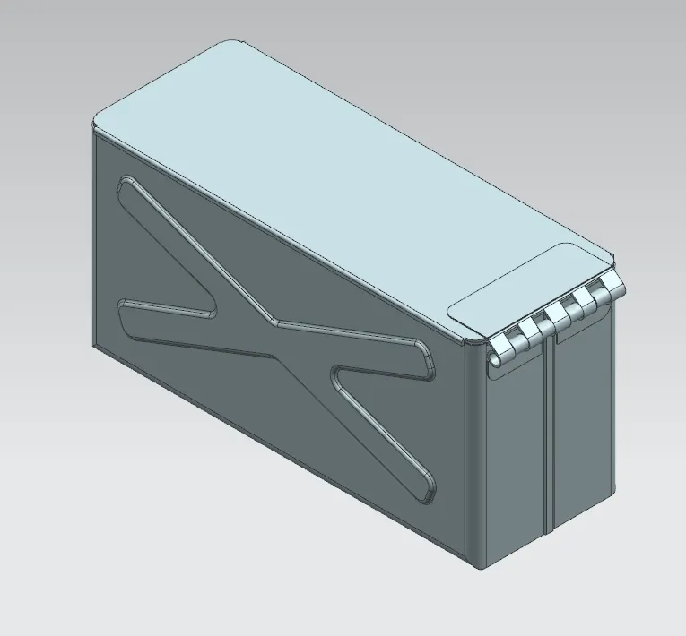
The Box is a sheet metal component that has been achieved using features such as tabs, flanges, cutouts and etc. The box is designed in such a way that it has a rectangular geometry with a top and a hinge between the wall and the top. It also has few detailings for making the box look attractive. Metal enclosure boxes serve a variety of purposes. From items such as lockboxes to filing cabinets, to more technical and ubiquitous uses such as electronics enclosures, you can find metal enclosure boxes just about anywhere. Depending on the use, the design of the item, and even the aesthetic, whatever use you have in mind for an enclosure box, there is a sheet metal out there that will work best for its fabrication. Sheet metal is cut, stamped, punched, sheared, formed, bent, welded, rolled, riveted, drilled, tapped, and machined. Hardware can be inserted into sheet metal components. The components can be brushed, plated, anodized, powder coated, spray painted, silk screened, or otherwise marked. And, of course, parts can be riveted, screwed, or welded into complex assemblies.
Design Methodolody:-
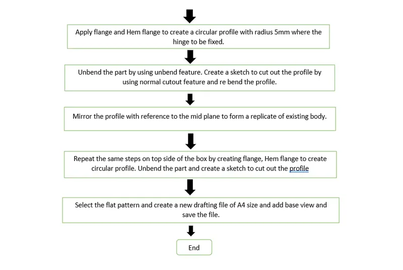
Description:-
All the tools and process used while designing the box assembly are as follows
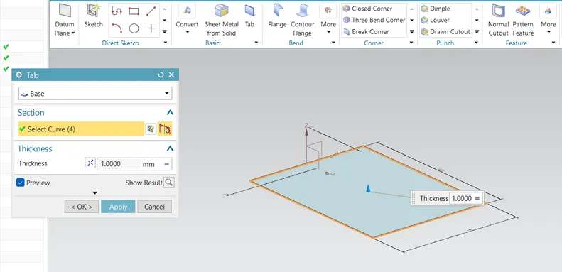
SKETCH: Adds curves, dimensions and constraints to a plane or face. Eg: Sketch about the XY plane of a rectangle to create the base feature.
TAB: Creates a base feature by extruding a sketch along a vector by a thickness value, or adds material to a planar face. Eg: The extrusion of the rectangular sketch.
NORMAL CUTOUT: Cuts material by projecting a sketch onto the model and then cutting perpendicular to the faces intersected by the projection. Eg: To cut a rectangles of the flange for hinge.
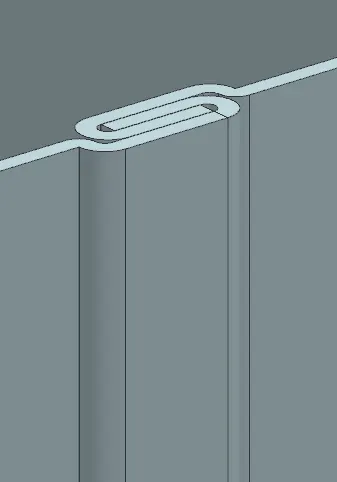
HEM FLANGE: Modifies the model by foliding the edge of a sheet metal flange over onto itself for the purpose of safe handling or to increase edge stiffness. Eg: The top edges of the flanges.
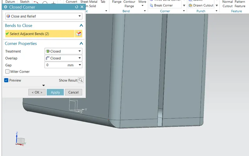
CLOSED CORNER: Closes a cornner where two adjacent flanges meet by extending the bends and flanges. Eg: To close the gap between the side walls.
MIRROR BODY: Copies a body and mirror it across a plane. Eg: Mirroring the half box.
UNITE: Combines the volume of two or more solid bodies into a single body. Eg: Combining the mirrored body.
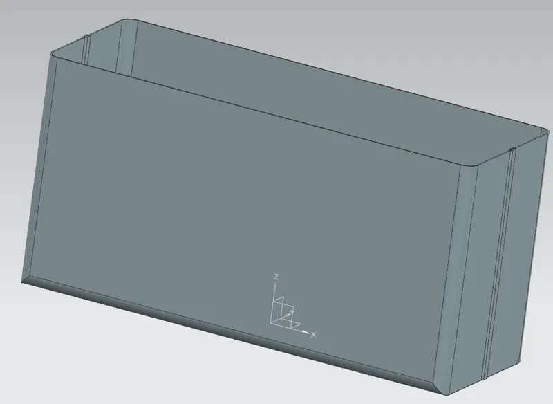
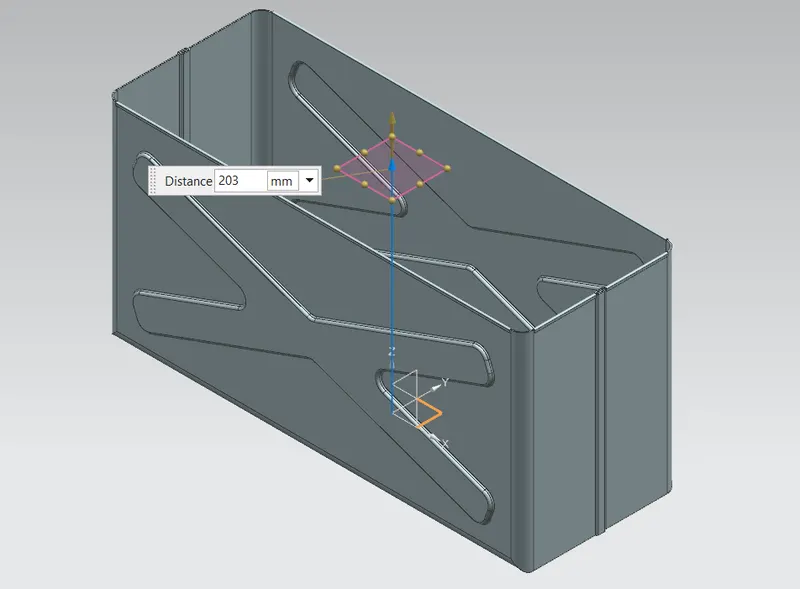
DATUM PLANE: Creates a datum plane used to construct other features. EG: Created an offset above the XY plane for the top of the box.
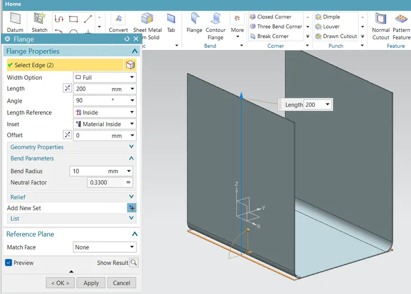
FLANGE: Adds a flat flange at an angle to a plane face and adds a bend between the two. Eg: Flanges to the edges of the tab to create the side walls.
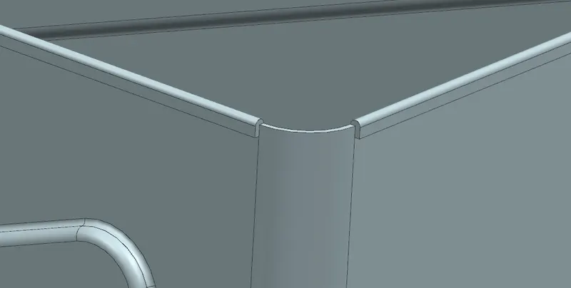
BREAK CORNER: Rounds or chamfers a sharp corner of a tab or flange. Eg: Applied to the corners of the tab for the hinge.
UNBEND: Flattens a bend and the material adjacent to the bend. Eg: To make the tab and flanges into a flat sheet.
DIMPLE: Lifts an area of the model inside a sketch that simulates a stamping tool. Eg: Lifting the cross shape of the side wall above the surface.
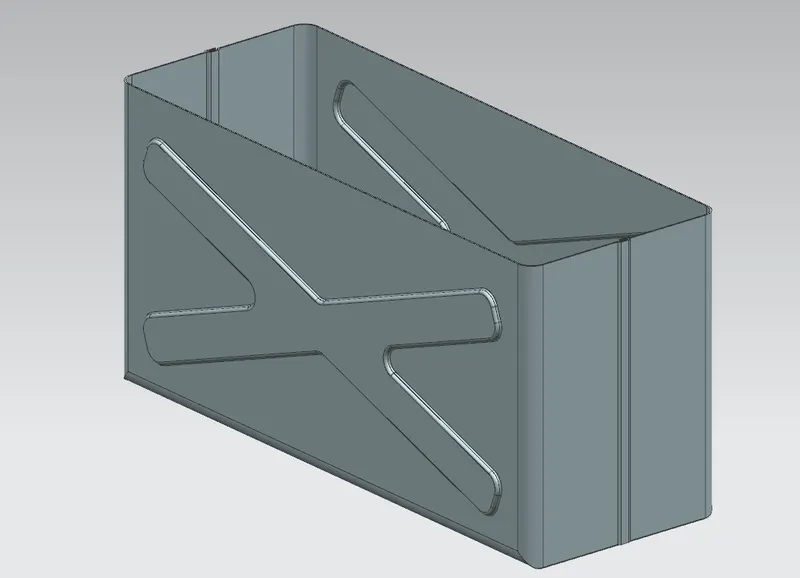
BEAD: Lifts material along the contour of a sketch the simulates a stamping tool. Eg: Circular sketches around the base.
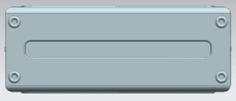
MIRROR FEATURE: Copies a feature and mirrors it across a plane. Eg: Mirroring the beads.
REBEND: Restores and unbend feature to its previous bent state, along with any features added after the unbend feature. Eg: Bringing back everything to previous bend.
DRAFTING: Application with tools to create and maintain drawings of the design model. Eg: Drawing with dimensions of the base view.
Images of a Box Assembly:-
FRONT VIEW:
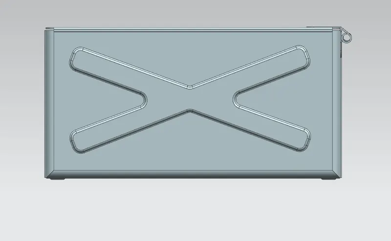
SIDE VIEW:
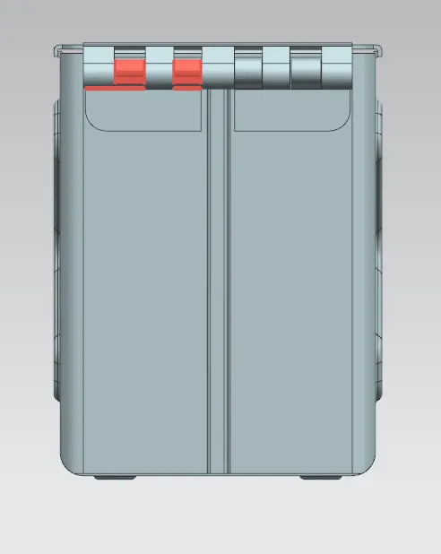
ISOMETRIC VIEW:
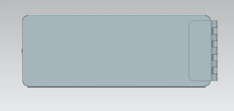
TOP VIEW:
Conclusion:-
Box Assembly has been designed by using NX application and learnt about the features.