Advanced Sheet Metal Design Using NX Cad Challenge_2_Box Assembly
Aim : To create a sheet Box assembly (Sheet metal component) and to understand the feature used in it.
Objective :
- To create CAD model of Box assembly and to understand the feature used in it .
- To create step bt step report of it.
Introduction :
- Sheet metal is formed by an industrial process into thin , flat sheet .
- It is used in metalworking , and it can be bent into a variety of shapes.
- Countless objects arefabricated using sheet metal .
- Parts manufacture from a sheet metal must maintain a uniorm thickness for ideal result.
Design methodology :
Description :
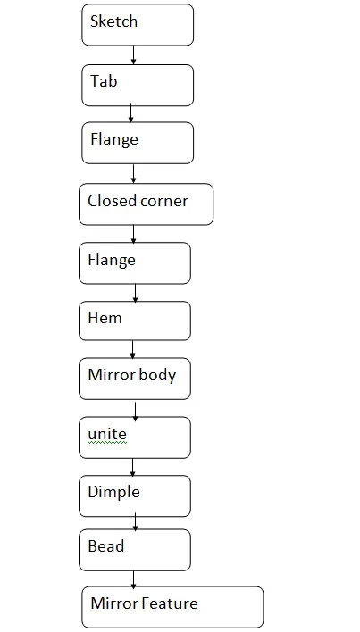
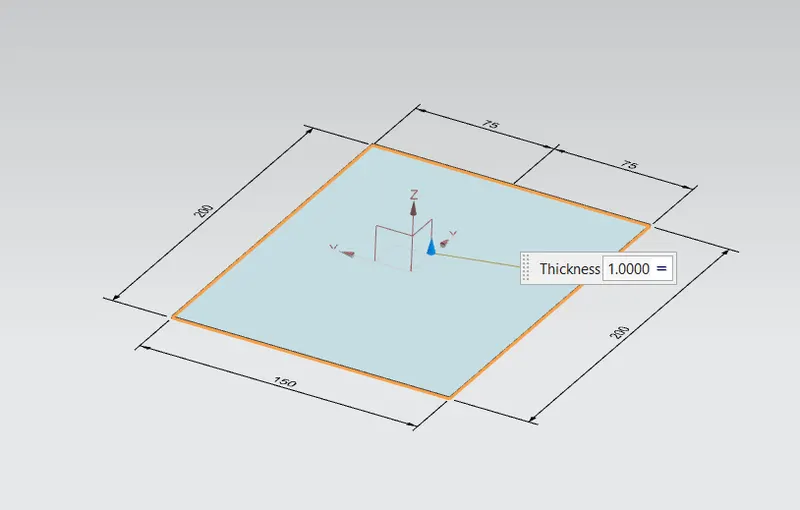
Tab :
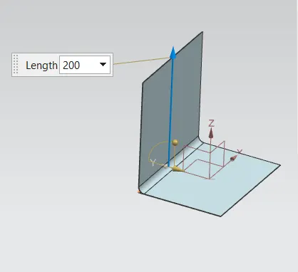
- It is a base feature that formed by extruding the sketch along a vector by providing thickness or add material to a plane.
Flange :
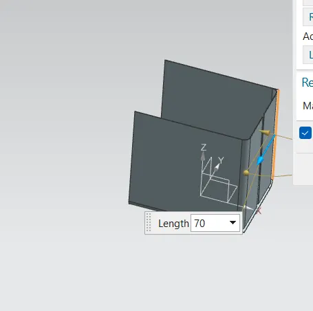
- Two flanges are provided at two side of base.
Closed corner :
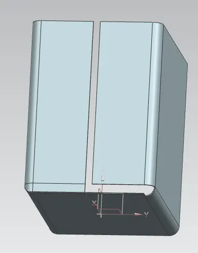
- It is used to fill the corner where two adjacent flanges meet .
Flanges :
- It is given to other side of 75 mm .
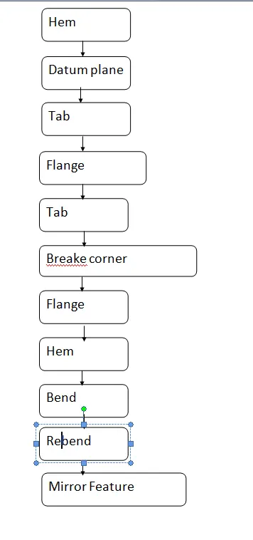
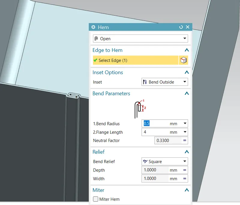
Hem :
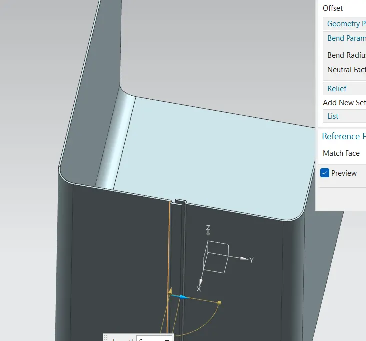
- It modifies the model by folding the edge of the flange over onto itself for the purpose of safe handling and to increase edge stiffness.
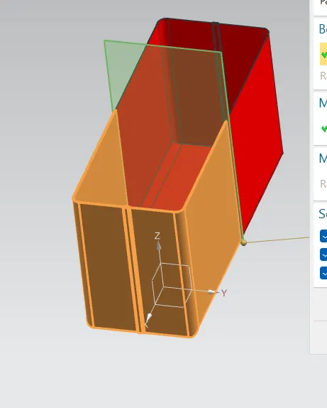
Mirror body :
- It is used to create mirror of the body .
- It is used to mirror a body along a plane .
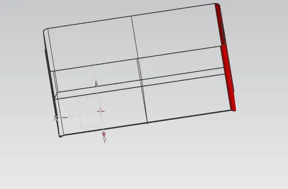
Unite :
- It is used to combine two parts of body or to joint the body.
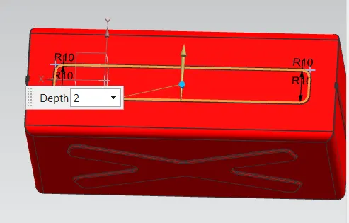
Dimple :
- It is used to lift the area tha simulates a stamping tool.
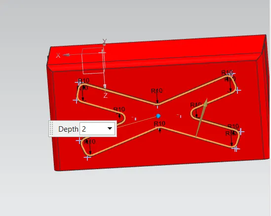
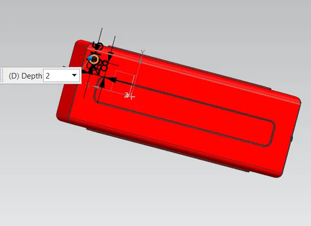
Bead :
- It lift the material along the contour of a sketch that form an stamping tool .
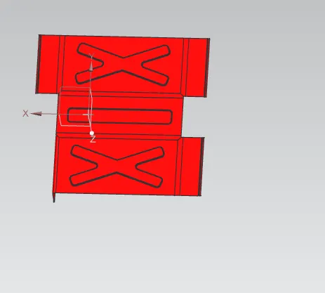
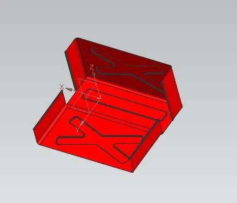
Unbend and rebend :
- For the manufacutring of the sheet metal , it is necessary to check the bend and rebend of the compont .
Hem flange:
- Flange is provided at the edge of flange to increase its strength.
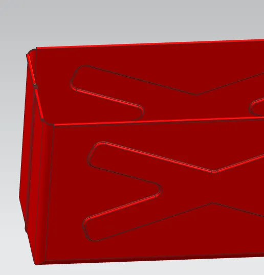
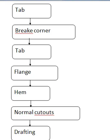
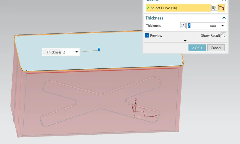
Tab :
- Here tab is used to creat a lid of the box .
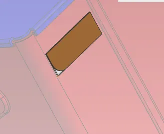
Breake corner :
- It is used to breake the sharpe corners at the edge .
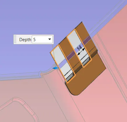
Normal cutouts :
- It is used to cut the section .
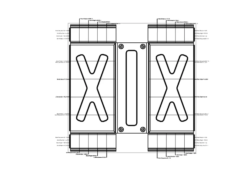
Drafting :
- It is used to convert 3D model into 2D model for manufacturing purpose .
Differnt view of model :
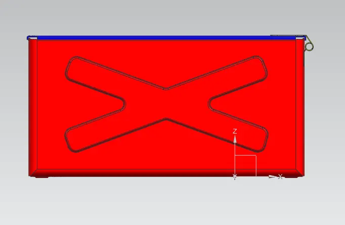
Front view:
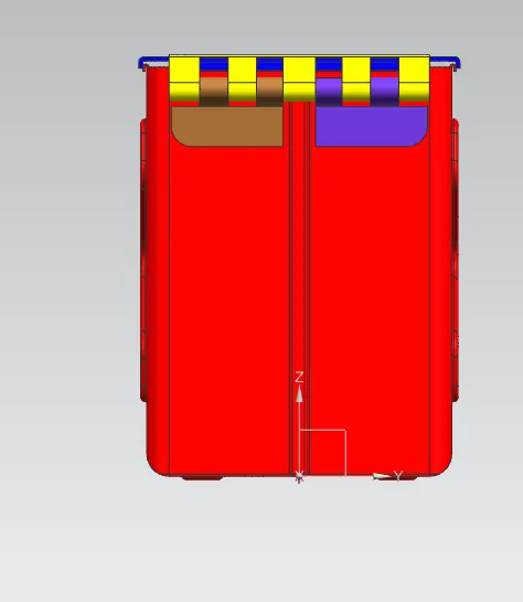
Right handside view :
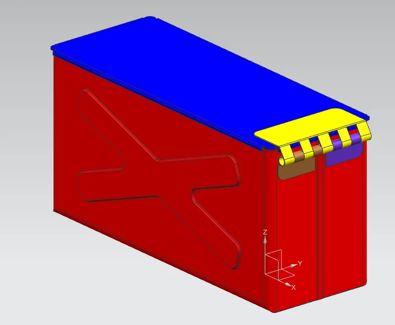
Trimetric view :
Flat pattern :
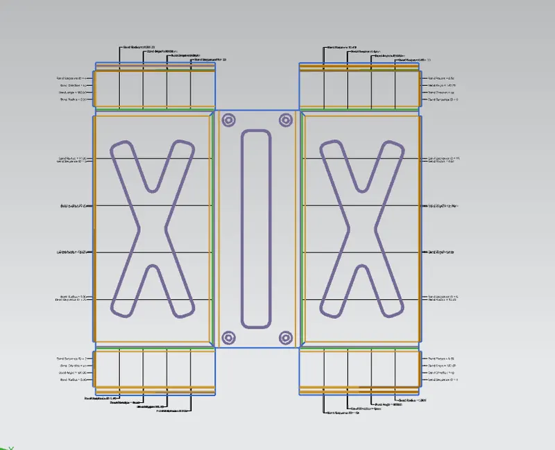
Drafting :
- Below is the picture of the drafting of the box assembly .
Conclusion :
- We have created the CAD model of the box assembly .
- Created drafting of the model.