Advanced Sheet Metal Design Using NX Cad Challenge_2_Box Assembly
TITLE: Box Assembly
OBJECTIVE: With the help of NX CAD tool, designing the sheet metal model of a Box Assembly.
INTRODUCTION:
Sheet metal is a metal formed by an industrial process into thin, flat pieces. It is one of the significant and basic form used in metalworking and it can be cut as well as bent into the variety of shapes.
Different metals such as brass, copper, aluminium, tin, steel, etc can be made into sheet metal. Sheetmetal is generally used in automobiles, wings as well as in other utensils. To manufacture all these in different designs and drafting in the specific way by a manual drawing can't be possible. So, the design tools are better options and object modeling can be done very easily.
In this Box Assembly model, we have used various sheet metal features like flange, hem flange, bead,dimple, break corner,etc. These features plays the significant part in the making of this model.
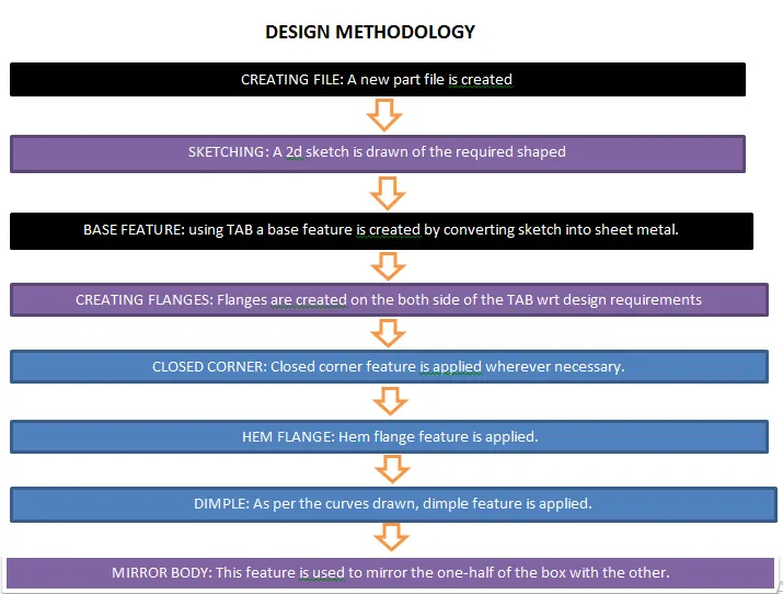
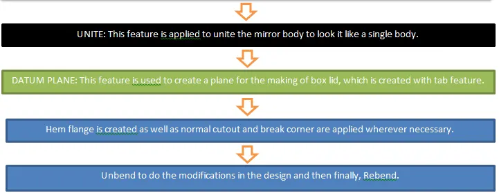
DESIGN METHODOLOGY:
DESCRIPTION:
Here, we will discuss about the various feature/tools used in the making of Box Assembly with the help of NX CAD.
- Sketch: This is used to create the basic sketch of the specific design on any desired plane.
- Tab: This is a sheet metal feature which help us to create a base tab by selecting the curve drawn in the sketch mode. Also, we can adjust our thickness value of the sheet in Tab feature or in the preferences.
- Flange: Flange works as a bend feature along with extra material that can be added adjusting the length of the flange.
- Closed Corners: This feature is used for closing the corners wherever two flanges are present.
- Hem Flange: Hem flange feature is used for variouse purposes. Here in the Box Assembly, we use it for easy holding.
- Dimple: It is used to create the indention in the sheet metal part or to uplift or downlift any area on the sheet metal part based on the sketch design.
- Mirror Body: This feature is used to create the copy of the body part in the opposite direction.
- Break corners: This feature is used to control the edges in various manners like making edges round for easy handling.
- Normal Cutout: It is used to cut the sheet metal part portions as per the sketch requirement.
- Unbend: This feature help us to analyze sheet metal part fully. It will the make the whole design into simple sheet metal plate where we can add any shape or adjustments if required which ensures smooth function of operations.
- Bend: Bending feature is used to bend the sheet metal along the sketch curves wherever it is required in the design.
- Beads: Generally used for strengthening the sheet metal part.
- Rebend: The feature is used when our sheet metal design part is ready for the production process after all confirmations and eradicating all errors.
BOX ASSEMBLY MODEL:
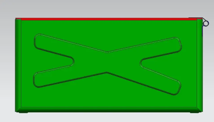
Front View
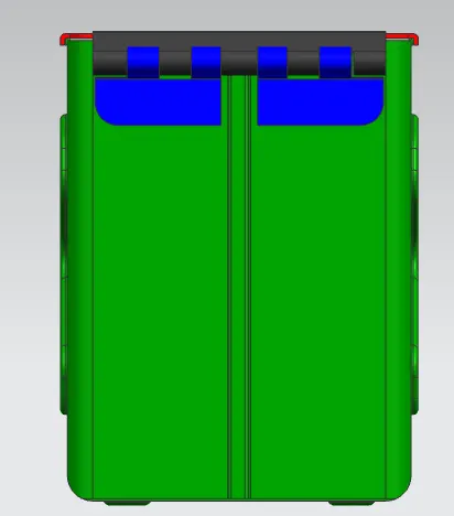
side view
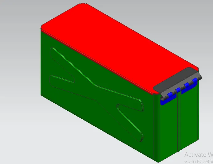
ISOMETRIC VIEW
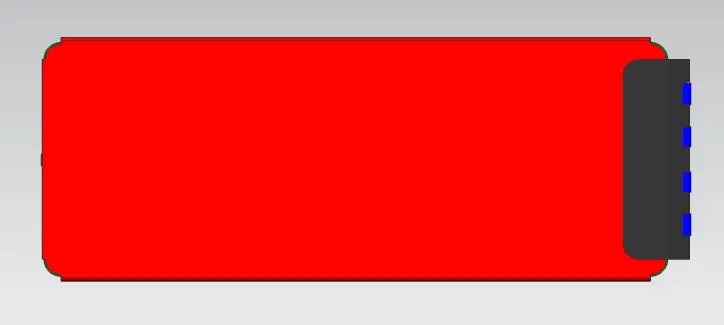
TOP VIEW
CONCLUSION:
In this challenge that is box assembly, i have learnt various advances features of sheetmetal using NX CAD tool.