Advanced Sheet Metal Design Using NX Cad Challenge_2_Box Assembly
Box Assmebly Design Using NX cad
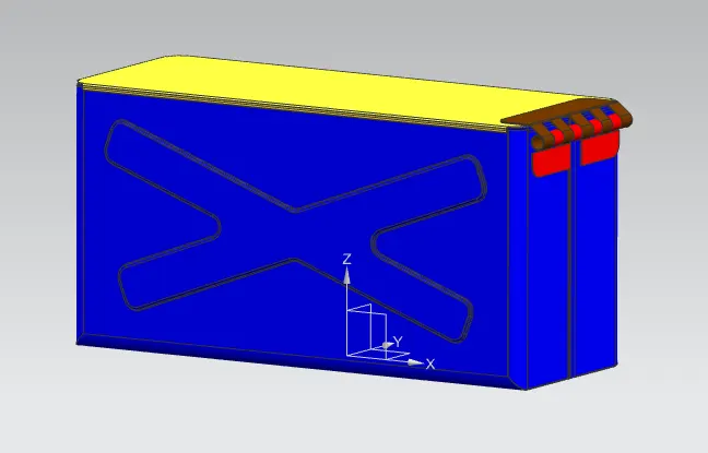
Objective -
To Design a Sheet metal box assembly using NX sheet metal workbench
Introduction -
Sheet metal is metal formed by an industrial process into thin, flat pieces. Sheet metal is one of the fundamental forms used in metalworking, and it can be cut and bent into a variety of shapes. Countless everyday objects are fabricated from sheet metal. Thicknesses can vary significantly; extremely thin sheets are considered foil or leaf, and pieces thicker than 6 mm (0.25 in) are considered plate steel or "structural steel".Sheet metal is available in flat pieces or coiled strips. The coils are formed by running a continuous sheet of metal through a roll slitter.In most of the world, sheet metal thickness is consistently specified in millimeters. In the U.S., the thickness of sheet metal is commonly specified by a traditional, non-linear measure known as its gauge. The larger the gauge number, the thinner the metal. Commonly used steel sheet metal ranges from 30 gauge to about 7 gauge. Gauge differs between ferrous (iron-based) metals and nonferrous metals such as aluminum or copper. Copper thickness, for example, is measured in ounces, representing the weight of copper contained in an area of one square foot. Parts manufactured from sheet metal must maintain a uniform thickness for ideal results.There are many different metals that can be made into sheet metal, such as aluminium, brass, copper, steel, tin, nickel and titanium. For decorative uses, some important sheet metals include silver, gold, and platinum (platinum sheet metal is also utilized as a catalyst).Sheet metal is used in automobile and truck (lorry) bodies, airplane fuselages and wings, medical tables, roofs for buildings (architecture), and many other applications. Sheet metal of iron and other materials with high magnetic permeability, also known as laminated steel cores, has applications in transformers and electric machines. Historically, an important use of sheet metal was in plate armor worn by cavalry, and sheet metal continues to have many decorative uses, including in horse tack. Sheet metal workers are also known as "tin bashers" (or "tin knockers"), a name derived from the hammering of panel seams when installing tin roofs.
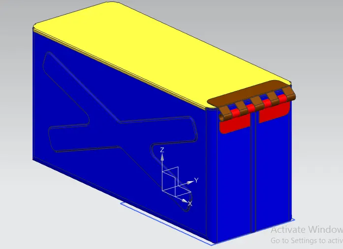
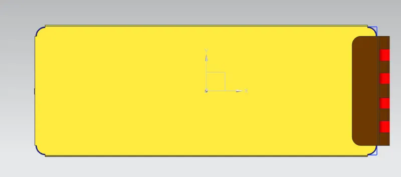
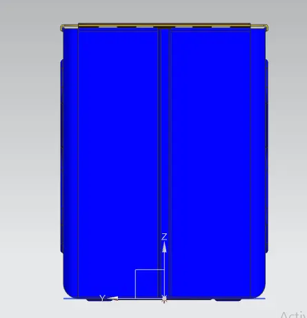
Sheet metal is a metal forming process through industrial process into thin, flat pieces. Here, I have created a Sheet Metal Boxassembly of Various thickened parts. Box assembly contains 3 main parts.
1. Box (base part)
2. Box Lid
3. Hinge
Design Methodology -
1. Box
1) Sketch
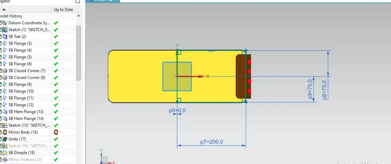
200mm x 150mm sized rectanglecreated on the XY plane of datum coordinate system
2) Tab
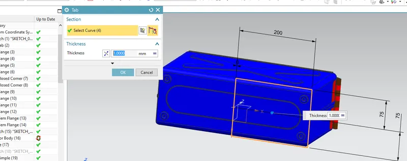
Base of the box created using sketch drawn in XY plane
3) Side Flanges
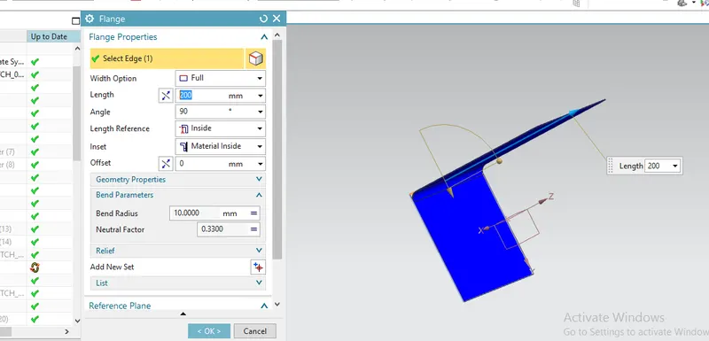
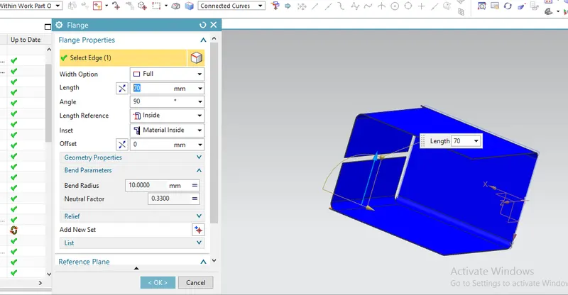
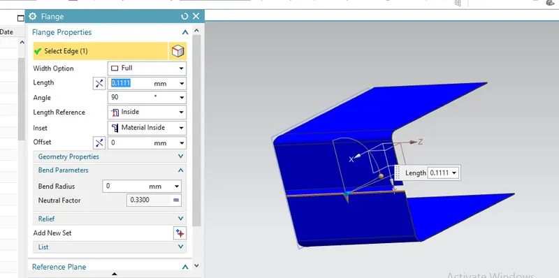
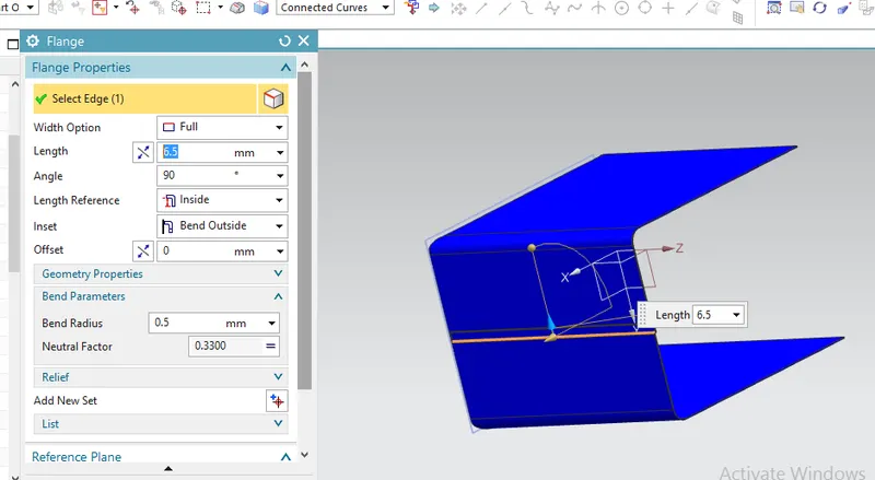
Side walls of the Box created using flange option
4) Closed corner
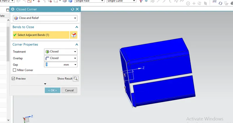
This tools used to Provide smooth corner by removing intersection, handling gap and smoothning ends of the flanges
5) Hem Flange
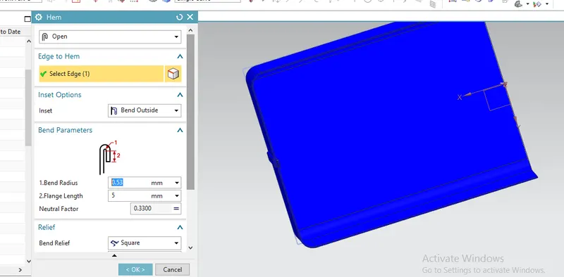
Close loop of Hem flange created at the open ends of the side walls to close the gap between flanges of side walls.
6) Mirror Body
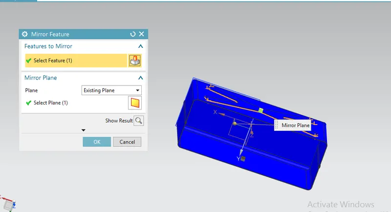
Body of the box completed by mirroring body.
6) Unite
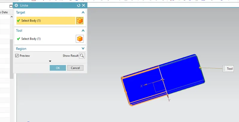
After using mirror body tool 2 saperate body created. This tool united those saperated bodies.
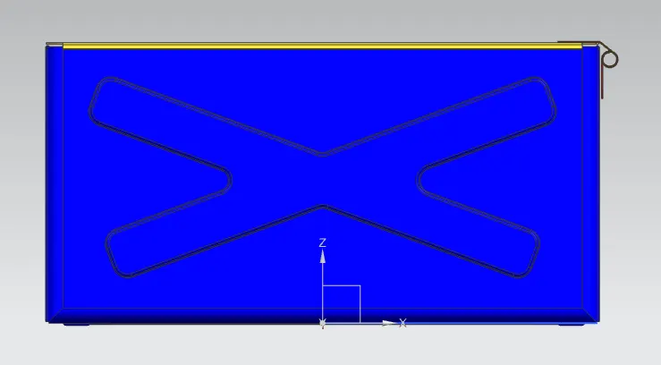
7) Dimple
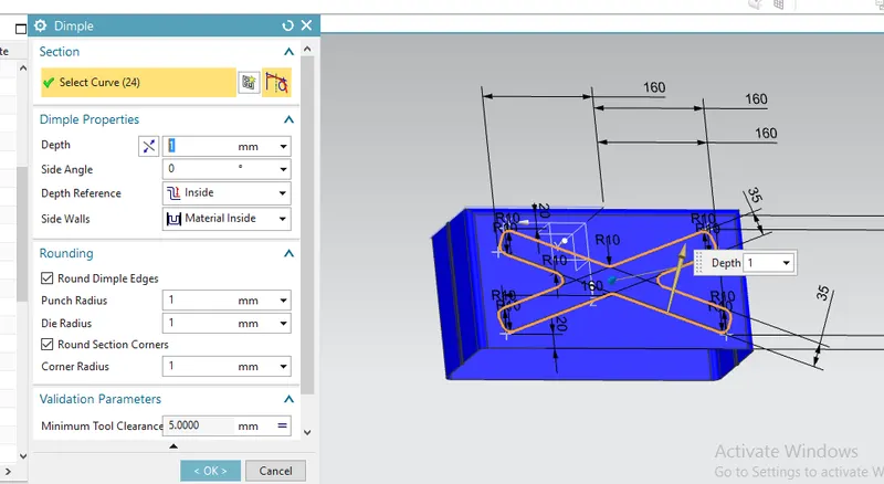
Embosses created on the body of the box to increase strength. Dimple tool used to create embosses..
First, I have created a sketch on the side wall of the box
8) Mirror Feature
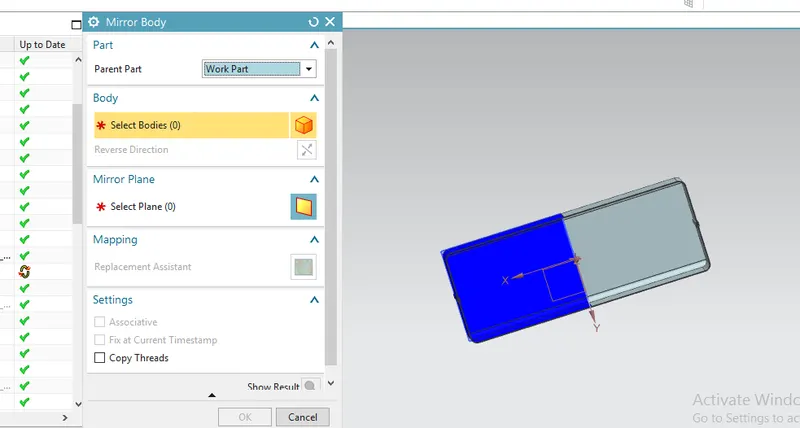
Emboss creted on other side of box (same as created above) created by using Mirror feature. This is a different tool than mirrorbody byt has same purpose. It mirrors features tht created on the body while mirror bdy mirrors the whole body.
9) Dimple
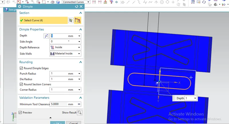
Again used dimple tool to create emboss on the bottom of the box. I have drawn a rectngle on the bottom face of the boxtocreate dimple there.
10) Bead, Mirror feature
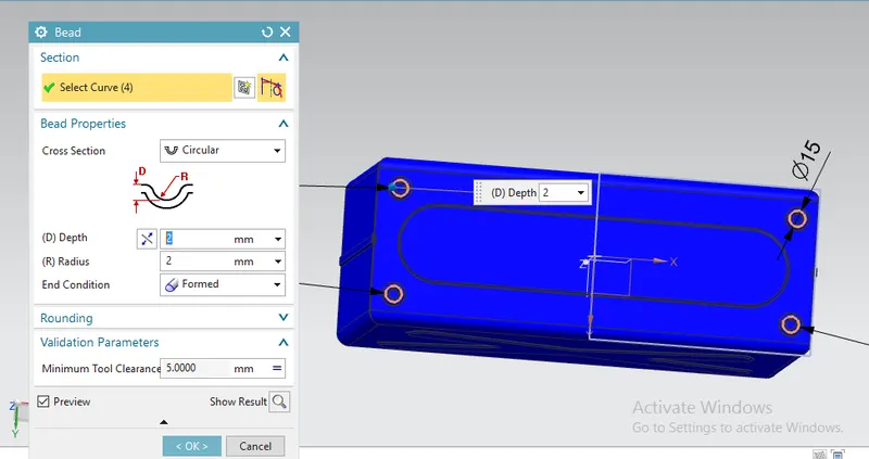
Bead created on the bottom of the box, sketch drawn for the bead attached below.
11) Hem Flange
Hem flange created on the sharp edges of the Box side walls
2. Box Lid
1) Datum plane
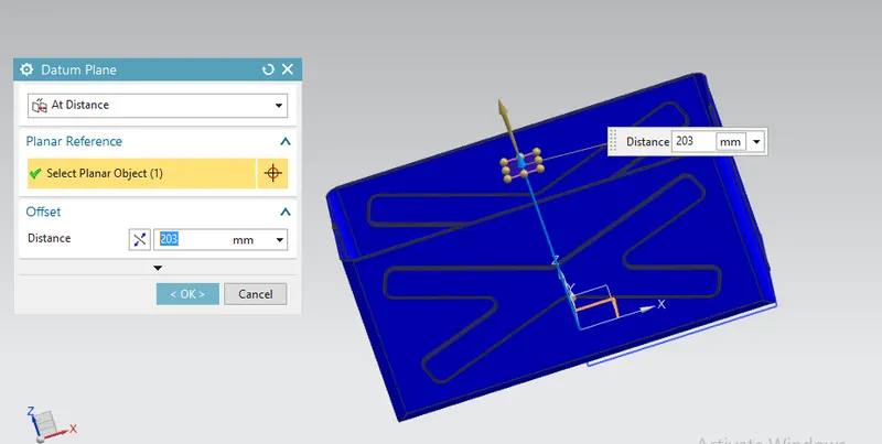
Datum plane w.r.t. XY plane of datum coordinte system to an offset of 203mm created.
2) Sketch
I have created sketch on the above created datum plane as a reference for Box lid
3) Tab
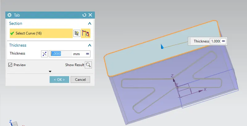
Box Lid created using Tab tool
4) Flange
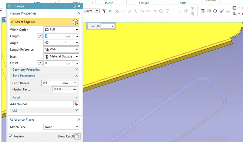
Flanges added at the 2 edges to complete the Box lid
3. Hinge
Here, Hinge created in 2 parts
1. Box Part
2. Box lid part
1) Tab
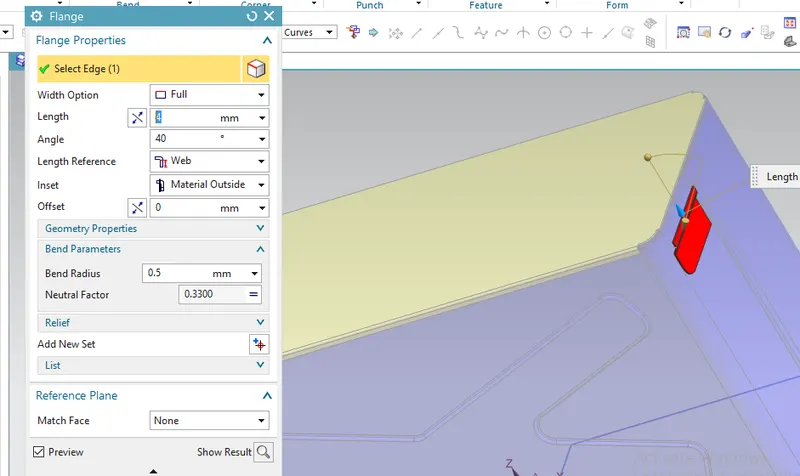
Base flange of the Hinge box part created using flange tools. Sketch created as on the side wall of the box.
2) Break Corner
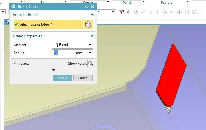
Corner blended with keeping 10mm radius
3) Flange
02 additional flanges created on w.r.t. base flange created above.
4) Hem Flange
Open loop of hem flange created
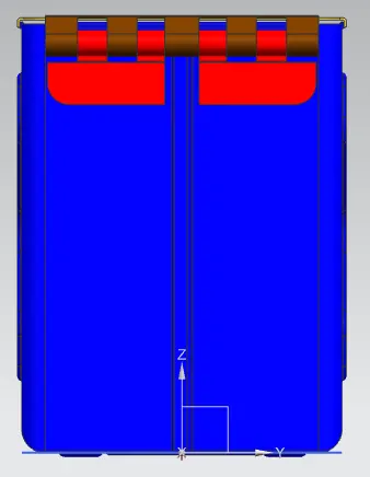
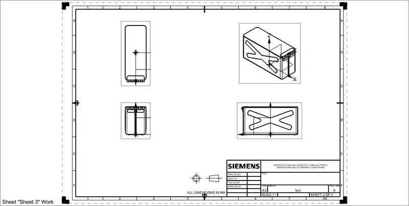
Drawing sheet
Conclusion -
By doing this project I have learned some new NX sheet metal work bench tools like Hem flange, Closed corner. Understood
the Design Methodology to create this type of sheet metal parts.