Radar Mast & Final Assembly of Yacht
SUNSEEKER PREDATOR YATCH
OBJECTIVE:
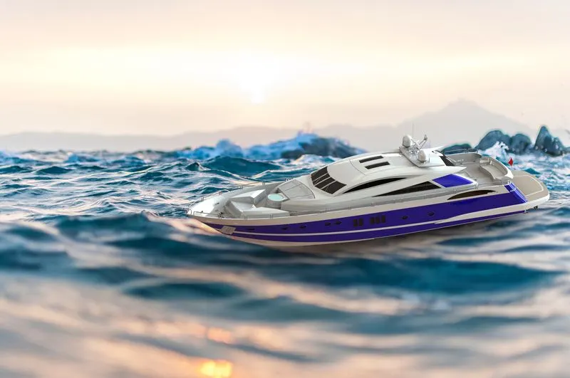
The objective of the project is to design and model all the parts of an Sunseeker Predator Yacht and assembling it to create the Photo-Realistic rendering of the yacht.
INTRODUCTION:
In this project the SUNSEEKER Predator Yacht was taken as a conceptual model, to understand the 3D modeling methodology of Solid modeling and Surface modeling. Each and eve, part of the yacht was designed and modeled using SOLID WORKS. Then the modeled parts were assembled by adding proper math and constraints to create the Photo-Realistic rendered image of the Yacht. The SOLID WORKS is a mechanical design automation application that lets designers quickly sketch out ideas, experiment with features and dimensions, and produce models and detailed drawings.
Parts to be modeled for SUNSEEKER PREDATOR YATCH : Following parts are modelded in solidwork and assemble together
1: Blueprint of SUNSEEKER PREDATOR YATCH
2: Hull
3: Super structure
4: Propeller
5: Garage door
6: Radar mast
7: Front seat
8: Middle seat
9: Rear seat
1.BLUEPRINT:
A blueprint is a reproduction of a technical drawing or engineering drawing using a contact print process on light-sensitive sheets. A blueprint is a guide for making something, if its a design or pattern that can be followed. They were easier to read and faster to make.
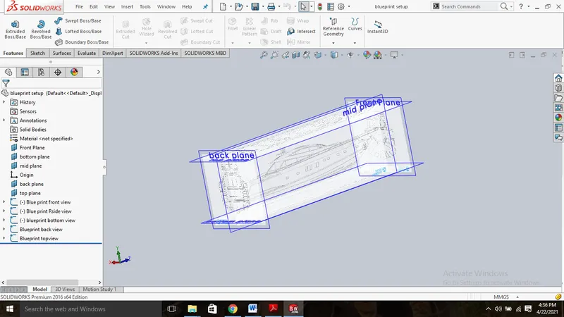
The above shown Blueprint was used to model the Yacht in a fully defined constraints. For setting up the Blueprint the Sketch pictures options were used and placed the different blueprints at the required planes.
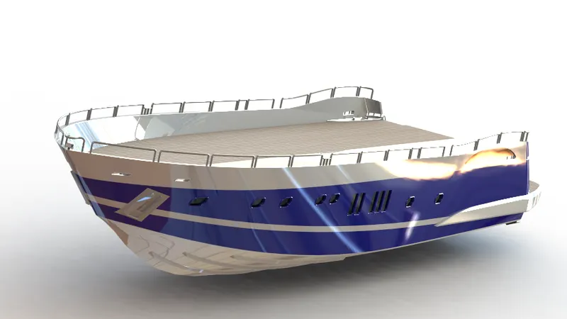
2: HULL
A hull is the watertight body of a ship or boat. The hull may open at the top (such as a dinghy), or it may he fully or partially covered with a deck. The line where the hull meets the water surface is caned the waterline. The hull of a ship is the most notable structural entity of the ship. To define the hull, it can be said that k is the watertight enclosure of the ship, which protects the cargo, machine, and accommodation spaces of the ship from the weather, flooding, and structural damage.
PROCEDURE:
The first step for modeling the Yacht was creating a blueprint of it.
Then the blue print was placed at the required planes, by using it first the hull was designed.
To get the shape of the hull the projected curve was produced by drawing the required sketch using splines with the help of blueprint.
Then the curves were lofted to create a lofted surface and the remaining unwanted surface was trimmed using surface trim.
Then the back portion of the hull were the propeller needs to be placed was extruded using Extruded Surface and all the surface created must
be Knitted together to remove the gaps between the surfaces.
Then the offset option was used and another surface was created and both surface was filled using surface fill to create the outer shell of the
hull which will be converted into a solid body at last.
To get the shape ot the hull the projected curve was produced by drawing the required sketch using splines with the help ot blueprint.
Then the curves were lofted to create a lofted surface and the remaining unwanted surface was trimmed using surface trim.
Then the back portion of the hull were the propeller needs to be placed was extruded using Extruded Surface and all the surface created must
be Knitted together to remove the gaps between the surfaces.
Then the offset option was used and another surface was created and both surface was filled using surface fill to create the outer shell of the
hull which will be converted into a solid body at last.
Shell feature was used to create the front portion of the hull where the deck surface meets. Then the deck surface was created using Extruded Boss/Base and Extruded Cut.
Then the required chamfers and fillets were created wherever necessary.
All the windows and Portholes were created using Extruded Cut and Fillets were add around the edges.
For creating the smooth edges around the berth window the reference plane were created and a circle for required dimensions were make
pierced and then swept around the edge of the windows.
The Rails at the bottom of the yacht were created using Extruded Boss/Base and the chamfers were applied both the sides.
The Cable Rollers were created using Extruded Boss/Base and Swept Boss/Base and the head part of it was created using Revolved Boss/Base
and Extruded Cut was used to cut through the extrude and a Dome was created over it. Helix/Spiral sketch was created to sweep the rope around the Cable Rollers.
By using Slot option the Rope hangers were extruded and the dome was applied and then the Linear Pattern was used to create one more.
The window bars were created using Extruded Boss/Base.
The staircase was created by using extruded boss/base and the hand support bar was created using Swept Boss/Base.
The Railings around the Hull was generated with the help of blueprint and the projected curve was produced and the railing reference was
swept using Swept Boss/3ase.
The Axles for the propeller and the surfer were created using Revolved Boss/Base option and using the 3d sketch.
The Anchors were created by sketching the first half and extruded using Extruded Boss/Base and the other half was mirrored.
The staircase was created by using extruded boss/base and the hand support bar was created using Swept Boss/Base.
The Railings around the Hull was generated with the help of blueprint and the projected curve was produced and the railing reference was
swept using Swept Boss/3ase.
The Axles for the propeller and the surfer were created using Revolved Boss/Base option and using the 3d sketch.
The Anchors were created by sketching the first half and extruded using Extruded Boss/Base and the other half was mirrored.
Finally the Garage Portion was created by using Extruded Cut and the portion was saved for later use by
using Split option.
By using the Split line option the Painting portion for our hull was split separately.
Then the other half of the Hull and the Axle of the surfer and propeller was mirrored to form the complete hull using Mirror tool.
Now the part was saved by adding proper appearances and fillets.
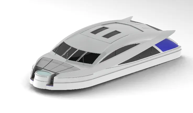
3.SUPER STRUCTURE:
A superstructure is an upward extension of an existing structure above a baseline called ground level and it usually serves the purpose of the Structure's intended use. A superstructure is a decked structure on the free board deck, extending from side to side of the ship.
PROCEDURE:
- The deck surface from the hull was imported and the superstructure was modelled over it.
- The side surface of the Superstructure was created by using Extruded Surface, Lofted Surface, Filled Surface, Trim Surface and Knit Surface.
- The Front side of the Superstructure was designed to have for rest beds which were created using Extruded Boss/Base, Fillets and Dome.
- The front edge of the superstructure was provided with a Water Feature which was created using Extruded Boss/Base, Extruded Cut, and filled with a water appearance. The Windshield was created by Extruded Cut and the wipers were created by using 3D sketch and reference plane with the help of Swept Boss/Base.
- The Portholes for the Superstructure were created by using Extruded Surface, Trim Surface and Extend
- Ruled Surface was used to fill the left out edges.
- The Back Doors of the Superstructure was created using Extruded Cut, Fillets and Reference Plane.
- Then all the surfaces generated were Knitted together to form a solid body.
- The Superstructure consist of two surface bodies and five solid bodies.
- One of the surface was the Deck Surface the other one was used to place the Radar Mast so it was renamed as Radar Mast reference Surface.
- Then the other half was mirrored and the proper fillets and appearance was added and finally the part was saved.
4.PROPELLER:
There can be one, two or three propellers. It is the most important part of the ship without which a ship can't move. So, the main function of It is the most important part of the ship without which a ship can't move. So, the main function of propeller is to propel the ship in the forward direction by producing thrust on water.
PROCEDURE :
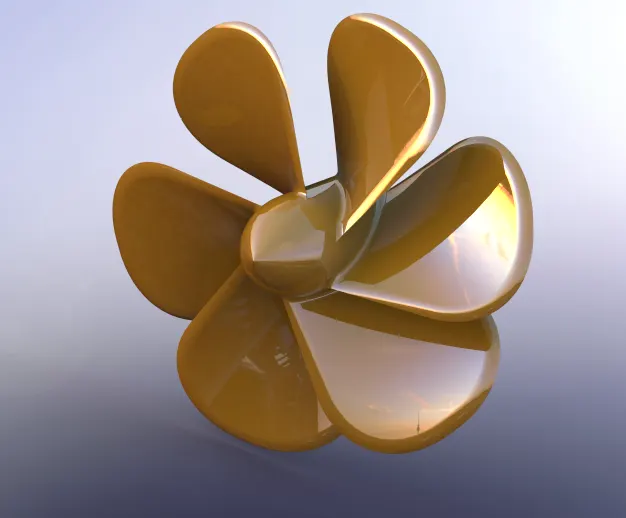
- The center portion of the Propeller was sketched and revolved using Revolved Boss/Base.
- Then the Blades were created using the Reference Plane, Lofted Boss/Base and Fillet. Then the remaining five blades were created by using Circular Pattern. Then the center circular portion was removed using Extruded Cut option. Finally the part was saved by adding the proper appearance.
5.GARAGE DOOR:
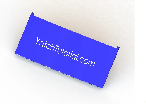
A garage door is a large door on a garage that opens either manually or by an electric motor (a garage door opener). Garage doors are frequently large enough to accommodate automobiles and other vehicles. The operating mechanism is spring-loaded or counterbalanced to offset the weight of the door and reduce human or motor effort required to operate the door. Less commonly, some garage doors slide or swing horizontally. Doors are made of wood, metal, or fiberglass, and may be insulated to prevent heat loss.
PROCEDURE
-
- By using the Extruded Cut the Chamfered face for the door was created.
- Then by using the shell feature the solid body for our garage door was created and proper fillets were
- Then the door holding on both sides were created using Extruded
- Then the second half of the Garage Door was created using Mirror tool after applying the required fillets.
- Then the text over the garage door “YATCHTUTORIAL.COM” was created using the text option in sketch feature.
- Finally the part was saved by applying proper appearance.The solid body split while creating the Hull was imported to model the Garage Door.
6.RADAR :
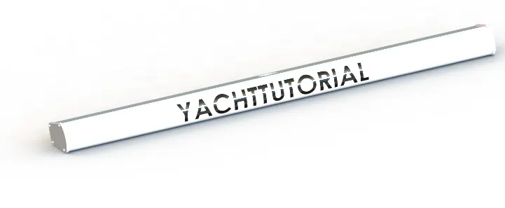
Marine radars are X band or S band radars on ships, used to detect other ships and land obstacle, to provide bearing and distance for collision avoidance and navigation at sea They are electronic navigation instruments that use a rotating antenna to sweep a narrow beam of microwaves around the water surface surrounding the ship to the horizon, detecting targets by microwaves reflected from them, generating a picture of the ship's surroundings on a display screen.
PROCEDURE
- By drawing the required sketch the body of the Radar was created using Extruded Boss/Base.
- By using the Sketch Pattern the four Dotted holes were created using Extruded Boss/Base and Extruded
- The Radar has a circular slot underneath which was created using the Extruded The other half was mirrored With the help of mirror tool
- The Text over the Radar was created using the Text option in sketch and then the Split Line was used to generate over the face of the radar.
- At last the radar must be filleted around the edges of the body and also around the four holes.
- Finally the part was saved by adding proper appearance.
7.RADAR MAST :
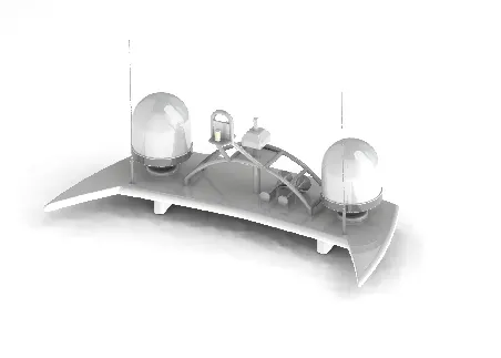
A mart is a vertical ship structure mounted on top of bridge and forward of the forecastle towards the ship's bow. It accounts for the support platform for the ships derrick and hold necessary equipment's such as radars, navigation light and ships horn in case of foremast They are made of high tensile steel with added rigidity based on the size of derricks it holds. Other than that a ships main mast is also used to hoist ships flag. Out of different parts of ship the main job of mast is to hold necessary equipment such as radar receiver, navigation lights. ships horn, flags in some case.
PROCEDURE:
- The first half of the Radar was Modelled with the help of blueprint and then the other half was mirrored with the help of Mirror tooL
- The body of the Radar*as created using Extruded Boss/Base and Revolved Boss/Base.
- The antenna for the radar was aLso created using the Extruded Boss/Base
- The horns were created using the Revolved Boss/Base, Dome and Shell.
- Then the fillets and chamfers were applied wherever necessary.
- Finally the part was saved by applying appropriate appearances. The lamp stand along with the connecting rod were created using the Swept Boss/Base and Mirror tool.
- 8. FRONT SEAT :
-
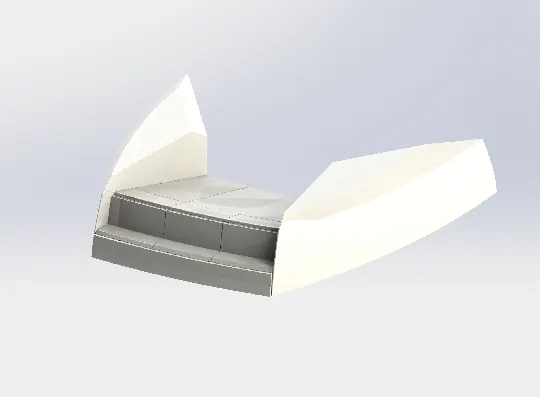
Front seat feature two connected seats that are built back-to-back horn one and other. They have a built-in storage unit undemeath them. Lounge seats can aLso fully recline right back to make it easier for you to kick your feet up and get more comfortable. The front seat in our model was placed before the superstructure and also it has sun pads to rest on is Sun pads are a great way to reclaim lost space on our boat.
-
-
PROCEDURE:
- The Front seat of the Yacht was aLso created with the help of Blueprint.
- The first half was modelled and the other half was mirrored using Mirror tool.
- The front seat was placed before the Superstructure facing the Water Feature of the Superstructure and the back end must be placed on the bow of the Yacht.
- The body of the Front Seat was modelled using Swept Surface, Extruded Surface, Filled Surface, Lofted surface and the unwanted part was removed using Trim Surface.
- Then the four Rest Beds were created using Extruded Boss/Base and the dome was created over the face of the beds separately.
- Then the required fillets and chamfers were created with extruded thin surfaces.
- Finally the part was saved by adding proper appearances.
- The lamp was created by using the projected curve and then the curve was swept using swept boss/base.
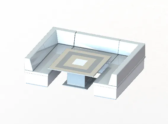
- The middle seat in our model was placed just behind the superstructure. It is provided with a luxury table to dine out. It can also be used to have casual meetings with co-passengers.
-
PROCEDURE:
- The Middle Seat was created using the Extruded Boss/Base and by applying the Chamfers and fillets as required
- The Dining Table was also created using Reference Plane, Extruded Boss/base, Off-set, Chamfers and Mirror.
- Then the second half of the Middle Seat must be Mirrored symmetrically.
- Finally the part was saved by applying the proper appearances.
10. REAR SEAT:
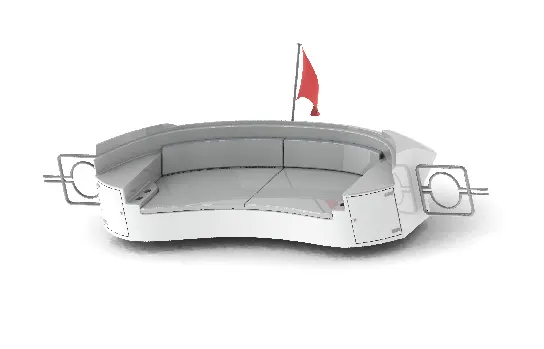
The rear seat was placed at the end of the deck surface. The rear seat consist of locker racks and steel doors for our stairs. The flag was also placed behind the rear seat since ifs the end part of our yacht. To have a nice view from the yacht while having a drink the rear seat was also provided with a slots to rest the glass or mug.
PROCEDURE:
- The main body of the Rear Seat was modelled using Swept Surface, Off-set Surface and the remaining portion was trimmed using Trim Surface tool.
- By using the Reference Plane the Seats were created with the help of Lofted Surface, Surface Trim and Extended Surface.
- The Flag Post was created using Revolved Boss/Base and the Flag was created by drawing the required 3D sketch and then the 3D sketches were lofted to form the Flag.To remove the gaps the all the Surfaces must be Knitted together using Knit Surface.
- • The required fillets and chamfer were created before mirroring the second half using Mirror tool and after mirroring the untreatedThe Tail Lamps were created by using Extruded Boss/8.e, Fillets and Mirror tool The Steel Gates For Stairs was designed by using the reference plane and the Swept Surface areas were filleted again.
- Finally the part w..ved by adding appropriate appearances.
- ASSEMBLY
-
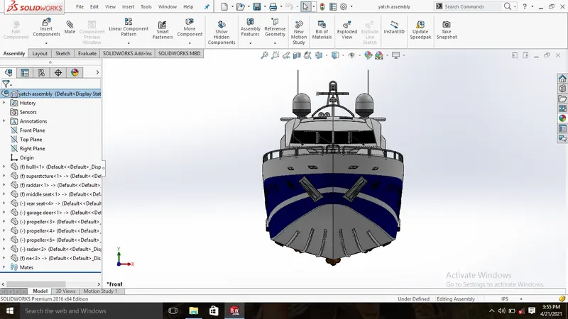
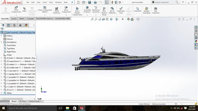
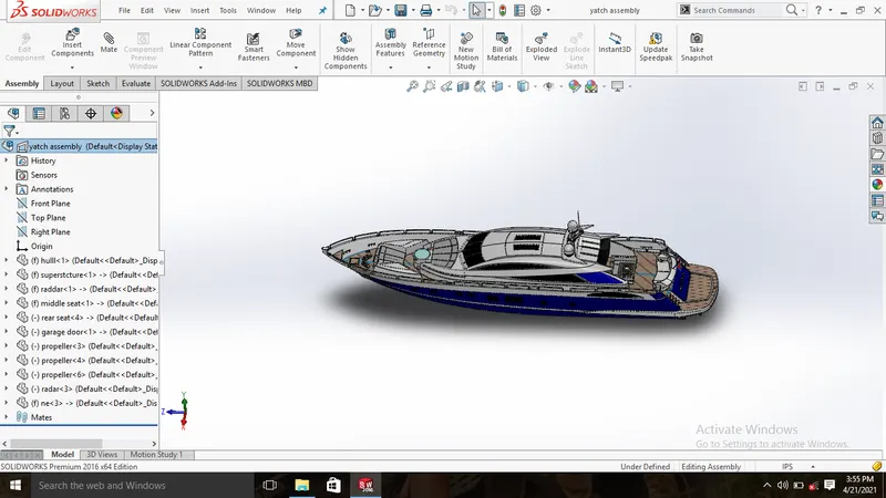
Combining multiple parts that fit together to create assemblies is called ASSEMBLY in SOLIDWORKS. We integrate the parts in an assembly using Mates, such as Concentric and Coincident. Mates define the allowable direction of movement of the components. An assembly is a collection of related parts saved in one SOLIDWORKS document file with a .sldasm extension. The components in an assembly are defined in relation to each other using assembly mates. The assembly components were attached using various types of mates such as coincident, concentric, and distance mates.
Assembly Design Methods Bottom-up Design
In bottom-up design, we create parts, insert them into an assembly, and mate them as required by our design. Bottom-up design is the preferred technique when we use previously constructed, off-the-shelf parts. An advantage of bottom-up design is that because components are designed independently, their relationships and regeneration behavior are simpler than in top-down design. Working bottom-up allows on to focus on the individual parts. It is a good method to use if we do not need to create references that control the size or shape of parts with respect to each other. Here in American chopper we use bottom up design hence the chopper is previously constructed model and in this project our chopper is designed as a custom model.
-
Top-down Design
In top-down design, we start our work in the assembly. We can use the geometry of one part to help define other parts, to create features that affect multiple parts, or to create machined features that are added only after the parts are assembled. For instance, we can start with a layout sketch or define fixed part Locations, then design the parts referencing these definitions. Top-down design is also known as in-context design. Combination of both the methods were also be used to create an assembly or subassemblies. In-Context Design We can create a new part within an assembly document (in the context of an assembly). In addition to creating or editing components in their own part windows, the SOLIDWORKS software lets us to create or edit components in the assembly window. The advantage is that we can reference the geometry of one component to create or modify another component. By referencing the geometry of another component, we ensure that the MATES: Mates position the components in an assembly precisely with respect to each other. Positioning the components defines how they move and rotate with respect to each other. Mates create geometric relations, such as coincident, perpendicular, and tangent. Each mate is valid for specific combinations of geometry such as cones, cylinders, planes, and extrusions.
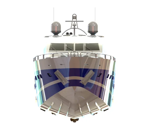
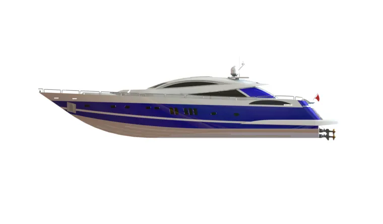
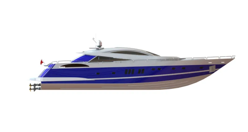
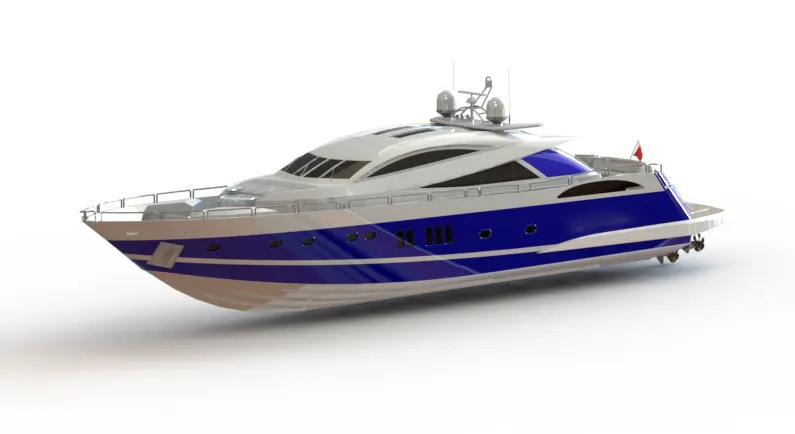
- SOME VIEWS OF YATCH ASSEMBLY
RENDERING:
Rendering of the Solidworks model is done using Photoview 360 and Solidworks Visualize.PhotoView 360 is a visualization and rendering solution included with SOLIDWORKS. Providing a highly interactive environment for viewing designs as well as tor creating photo-realistic renderings it can be used to showcase our designs. SOLIDWORKS Visualize (former y known as Bunk speed) provides a suite of standalone software tools that combine industry-leading rendering capabilities with visual design-oriented features and work owes, allowing easy and fast creation of visual content that communicates a design's vision, passion, and emotion."PhotoView 360 is distinguished from RealView in that it is not a process of the GPU,and photorealistic renderings can be achieved regardless of the graphics card used.
Procedural Appearances
Procedural appearances are defined by some procedure and consist of one or more cobra and the way the appearance reacts to light. Procedural appearances can be thought of as 3D, that is they go all the way through the part. This is like adding dye to a plastic to be injected; the color will go all the way through the finished part.
Texture Appearances
Texture appearances are applied Like wallpaper. During application, they can be stretched, shrunk, rotated, and reoriented to make them fit the surface. The pat-tern will be duplicated as many times as necessary to cover the entire surface. Lighting Lights may he added in the same way a photographer adds tights when taking photographs. PhotoView 360 uses the same lights as SolidWorks but also uses lighting from the rendering environment or scene. PhotoView 360 has the sophistication to trace tight rays and reflections.
Scenes
Each SolidWorks model is associated with a PhotoView 360 scene. for which you can specify properties such as environments and backgrounds. Scenes help to put products In context.
Decals Images, such as company logos, can be applied to models.
Output
The rendered output horn PhotoView 360 can be viewed on the screen, or saved to a graphics file.
Options
PhotoView 360 has its own options. Options allow you to customize the PhotoView 360 settings to reflect your preferences. Options are divided Into Output Image Settings, Render Quality, Bloom, Contour Rendering and Direct Caustics. PhotoView 360 scenes are made up of the things we see in the rendering that are not the model. They can be thought of as a virtual sphere around the model. Scenes are composed of backgrounds, foreground effects, and scenery. PhotoView 360 has numerous predefined scenes to make Initial renderings quick and easy.
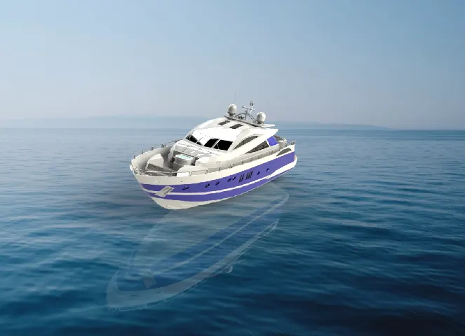
RENDERED IMAGES OF THE YACHT :