Project 1
Assembly Of TABLE FAN CASE (Mold design)
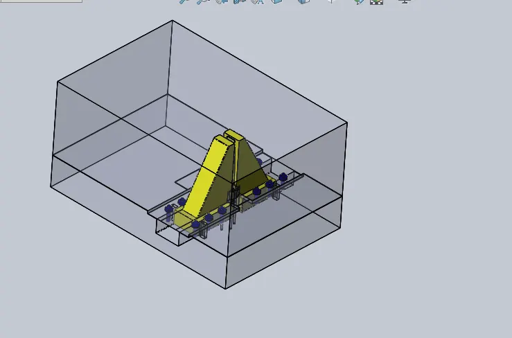
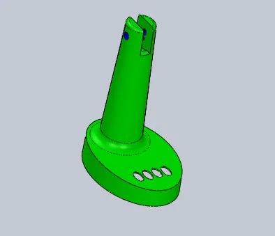
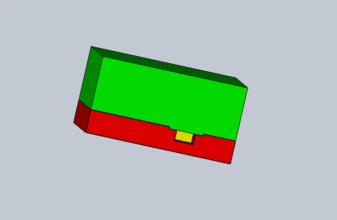
Objective: The objective of this project is used to create mold design a model of diffrent parts of the mold using solidwork.
Create an assembly of the diffrent parts modeled for the table fan case.
What is the mold design ?
Mould design is an important part of the development process when considering the production of a new moulding. Some considerations are given below.
- •The shape of the moulded part has a direct bearing on the time involved in making the mould, the cycle time of the moulding. For example, undercuts and deep screw threads often require a separate moving part which increases the cycle time of each moulding operation.
- •Angles on the side walls are necessary to ensure the moulding can be removed from the mould.
- •The surface finish of the moulding needs to be decided before the mould is completed. Embossing, etching and other finishes can be added to the moulding to enhance the aesthetic qualities of the moulding. Any imperfection on the finish of the moulding will transfer to every mould made.
- •Weight, surface area and thickness of the moulding directly affect cycle time. Where mouldings have significantly varying thickness, cooling has to be controlled very carefully otherwise depressions form (sink marks) on the outer surface of the moulding caused by excessive shrinkage of the thick section of the moulding.
- •The number of cavities in a mould is governed by the number of units per annum required. The number of cavities directly affects the size of machine required for the multi-cavity mould; this in turn affects the cost of the mould and the unit cost of the moulding. Where there are many cavities, each one must be uniform compared to the others and the cooling profile needs to ensure that the outer and inner cavities cool at an equal rate, otherwise moulds of differing dimension will result. Hot runner systems are usually used for multi-cavity systems. This reduces the cycle time and amount of waste material formed but increases the overall cost of moulds
- •The need for an insert or label to be inserted during the moulding sequence has to be considered at the mould design stage.
- •All injection moulds require a point or points at which the molten plastic is introduced into them. If not considered at the design stage, this can leave unsightly surface blemishes on the finished moulding which require a further stage to remove them, incurring extra costs.
Successful removal of the moulding from the mould is another critical consideration in mould design. Some mouldings, such as closures, have undercuts, which complicates the mould design. Sometimes the moulding is flexible enough, and the undercut small enough to pop or blow it off the tooling without damaging the moulding. However, this is not always the case and a more complex mould design may be required . Other options are the use of a collapsible core or, in the case of threaded mouldings, the incorporation of an unscrewing device.
Step to followed to create mold design using solidwork:
You create a mold using a sequence of integrated tools that control the mold creation process. You can use these mold tools to analyze and correct deficiencies with either SOLIDWORKS or imported models of parts to be molded.
Mold tools span from initial analysis to creating the tooling split. The result of the tooling split is a multibody part containing separate bodies for the molded part, the core, and the cavity, plus other optional bodies such as side cores. The multibody part file maintains your design intent in one convenient location. Changes to the molded part are automatically reflected in the tooling bodies.
 |
Draft Analysis | Examines the faces of the model for sufficient draft, to ensure that the part ejects properly from the tooling.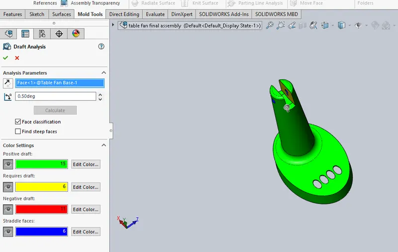 |
 |
Undercut Analysis | Identifies trapped areas that prevent the part from ejecting. |
 |
Parting Line Analysis | Analyzes transitions between positive and negative draft to visualize and optimize possible parting lines. |
 |
Parting Lines | This tool has two functions:
|
 |
Shut-off Surfaces | Creates surface patches to close up through holes in the molded part. |
 |
Parting Surfaces | Extrude from the parting line to separate mold cavity from core. You can also use a parting surface to create an interlock surface. See Interlock Surface. |
 |
Ruled Surface | Adds draft to surfaces on imported models. You can also use the Ruled Surface tool to create an interlock surface.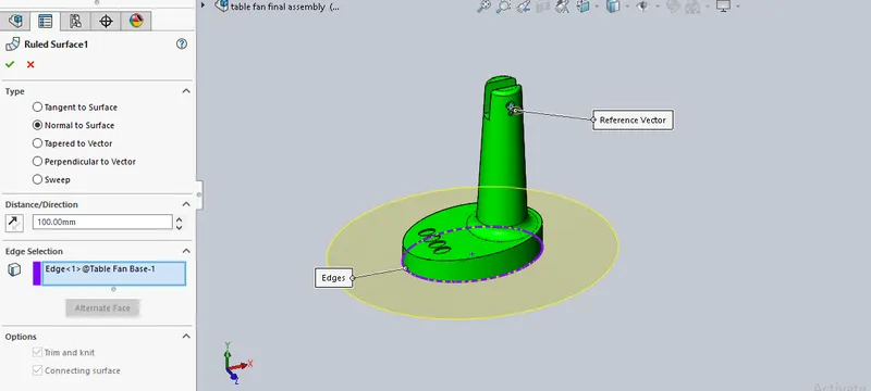 |
 |
Tooling Split |
Creates the core and cavity bodies, based on the steps followed earlier. |
 to all edges.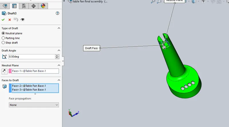
Parts to be modelded for TABLE FAN CASE: Following parts are modelded in solidwork assembly
1: core
2:cavity
3: slider 01
4: slider 02
5:washers
6:ejector pins
Now we will see each and Every part one by one in details
1: CORE:
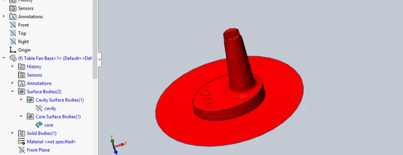
1:Firtly we add a part in assembly and then editing that part
2:change name that part to core
3:create sketch of the core box accourding to the requriment
4:convert into solid body
5:then using main core suface we did surface offset of 0
6:then uses cut with surface coomand to cut solid part in shape of core box(direction in upword)
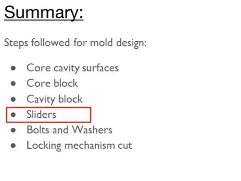
7:there are some undercuts so sliders are added in the core and caity for that we usues split command to split the slider and core
8:create space to slide the slider properly
9:create the space to accomadte washers in the core by using hold wizard command
10:create a cut for locking mechanism for slider
11:added fillet of 2mm
2:cavity:
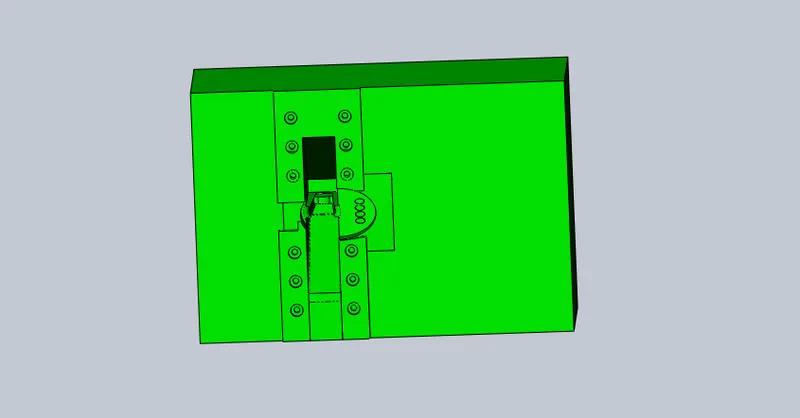
1:Firtly we add a part in assembly and then editing that part
2:change name that part to cavity
3:create sketch of the core box accourding to the requriment
4:convert into solid body
5:then using main cavity suface we did surface offset of 0
6:then uses cut with surface coomand to cut solid part in shape of cavity box(direction in downword)
7:there are some undercuts so sliders are added in the core and caity for that we usues split command to split the slider and cavity
8: fill the gap by adding solid body
9:create the space to accomadte slider in cavity by using combine coomand
10:create a space to accomadte washers in the cavity
11:added fillet of 2mm
3: slider 01 :
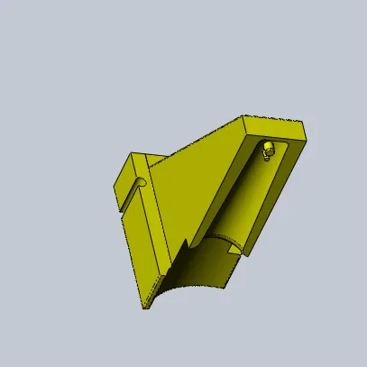
1:Firtly we add a part in assembly and then editing that part
2:change name that part to slider 01
3:import the slider body by using import
4:add wedge to the slider
5:resize the slider accourding to the need
6: create the coler in slider
7:adding space to accoamde washers
8:3mm hole foe locking mechanism in slider
9:added fillet of 2mm
4: slider 02 :
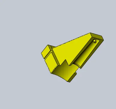
1:Firtly we add a part in assembly and then editing that part
2:change name that part to slider 02
3:import the slider body by using import
4:add wedge to the slider
5:resize the slider accourding to the need
6: create the coler in slider
7:adding space to accoamde washers
8:3mm hole foe locking mechanism in slider
9:added fillet of 2mm
5:washers :
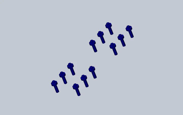
1:core we start editing the part started sketching the proper dimension washers in the core and then extruded
2:save the solid body of washers in the parasolid form
3:we add a part in assembly and then editing that part
4:change name that part to washers
5:import the file of washers
6:ejector pins:
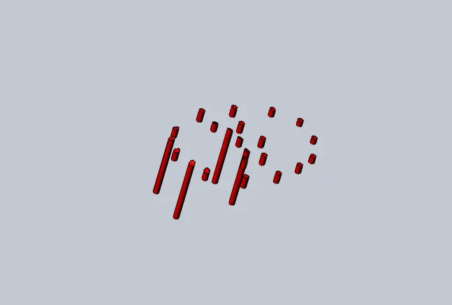
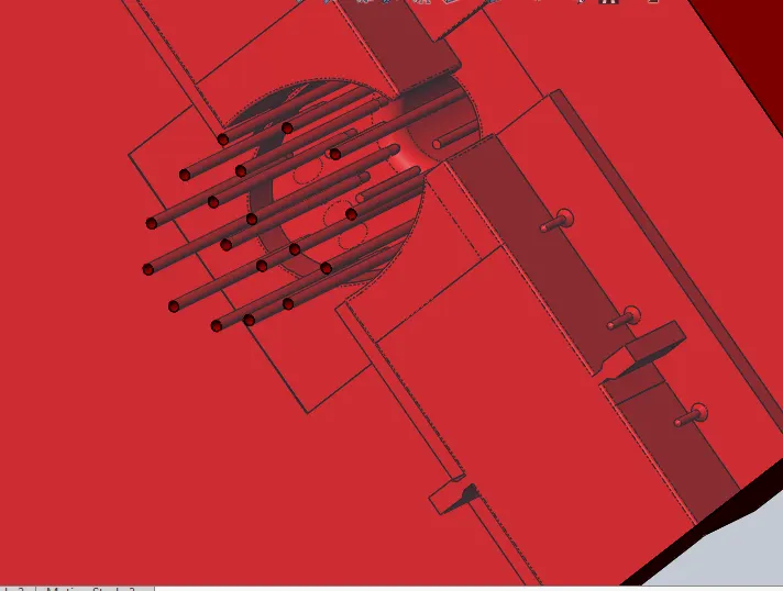
1:core we start editing the part started sketching the proper dimension ejector pins on the where they req (uses 6mm pins )
2:using that sket uses the core coomand to create pins
3:created new sketch to proved relief to pins (uses 6.95mm diameter circle)
4: using that sketch created cut extrude offset of 10mm from face of pins
Conclusion:
The part of the table fan case are modeled using most of the solid mold tools and assembly solidworks.The parts are inserted into the assembly environment and the table fan case is assembled.Getting used to with assembly & mold design module of solidworks