Advanced Sheet Metal Design Using NX Cad Challenge_2_Box Assembly
BOX ASSEMBLY IN ADVANCED SHEET METAL DESIGN USING NX CAD
Objective:
To design a Sheet Metal Box Assembly using Siemens NX Sheet metal application.
Introduction:
The Sheet metal application provides an environment for the design of sheet metal parts used in Machinery, Automotive and Aerospace. Enclosures, Brackets and other parts are normally manufactured with break press. The sheet metal application are widely used in the,
- Aircraft Bodies
- Automobiles
- Utensils used for domestic purpose
- Beverage cans
In sheet metal application we can create a uniform thickness sheet metal parts using basic features such as flange, tabs and jogs. We can also do close corners, cutout and stiffening features. The complex sheet metal part can be designed in the solid model workbench and then we can convert into a sheet metal part. We can also import, clean up and convert a non-sheetmetal part into a valid sheet metal part. Flat pattern sheet metal data can be used for the manufacturing process. The material parameters such as thickness, bend radii and bend relief can be easily set as default settings.
Design Methodology:
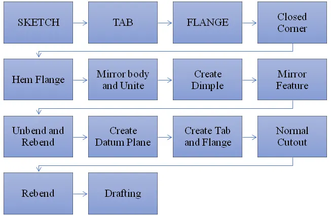
Description:
Sketch: A Sketch is a named set of 2D curves and points located on a specified plane or path. You can apply rules, in the form of geometric and dimensional constraints, to establish the criteria your design needs. Features created from a sketch are associated with it, if the sketch changes so do the features
Tab : create a base feature by extruding a sketch along a vector by a thickness value, or by adding material to existing faces and bend regions of a sheet metal part.
Flange: Flange command use to add a flat flange at an angle to a planar face and adds a blend between the two.
- Click flange command icon.
- In the graphics window, select the edge to add a flat flange.
- In the flange properties group.
- Select full option in the width option list.
- Set the length value in the length box. Click to change the direction if you want. In the length reference box, you can select more option as: inside, outside web, tangent.
- Select the angle of flat flange.
- In the inset box, you can select the method to inset material as: material inside, material outside, bend outside, material inside OML.
- Select the offset you want.
- Click OK to finish this command.
Note: If you want to use a different bend radius value, you need to draw arcs in the section, or change the default bend radius value.
Datum plane: It creates a datum plane used to construct other features. It is created to form the lid.
Mirror Feature: This is used to mirror a feature along a specific direction.
Unbend: This feature is used to unbend the sheet metal taking any one face as a stationary face.
Rebend: It uses after the “Unbend” command If needed.
To activate command:
- Click command on (When sheet metal application activated.) “ Home => Form Gallery => Rebend”
- Activate command from “Menu => Insert => Form=> Rebend
- Select unbent faces on the model. (“Select Face” in the “Bend” tab highlighted automatically when command activated.)
- If you want to define stationary face on sheet metal model, click down arrow in the command window to open more options. Click on “Select Face or Edge“ in the “Stationery Face or Edge” tab in the command window. The function will be highlighted. Select stationary face on the model.
- Click the “Ok” to finish
Dimple: The Dimple command to lift an area of the model inside a sketch that simulates a stamping tool. A Dimple feature across cylindrical bends in the unbent state. An open or closed section type of the Dimple feature can be created across a bend and a planar face, or completely inside the bend
Bead: Used for giving strength to the sheet metals
Bead command to lift material along the contour of a sketch that simulates a stamping tool. Beads can also be created to stiffen sheet metal parts.
- Choose Weld Assistant tab→Sealer group→Bead.
Hem Flange: Command to modify an edge of a sheet metal part by folding it onto itself for the purpose of safe handling or to increase edge stiffness.
The hem flange is always created as a secondary feature on a base part.
You can create hem flanges on:
- Linear edges and curved edges of the base part.
- Connected curves that include a curved edge. You can also create a flange on the linear edge of such hem flanges.
In the following example, a flange is created on the linear edge of a hem flange, and then both flanges are flattened
Flat pattern: Flat pattern is used to create flat pattern view which is used for drafting purposes.
Normal Cutout: Normal Cutout command to cut material by projecting a sketch onto the model and then cutting perpendicular to the faces intersected by the projection.
Closed Corner: Closed Corner command to modify two flanges in one operation and to close the corner where the two flanges meet. During flattening, the corner and relief geometry are made appropriate for a flat pattern.
When you use the Closed Corner command, you can create:
- Mitered closed corners on bends that have unequal bend radii or bend angles.
- Overlapping webs with mitered corners. This is applicable for the Close and Relief type of Closed Corner feature.
- Corners between flanges that bend in opposite directions.
- Corners between a wide range of corner angles.
- Mitered closed corners with a smooth transition from the miter to the cutout edges for the Circular Cutout , U Cutout , V Cutout , or Rectangular Cutout type of corner treatment options.
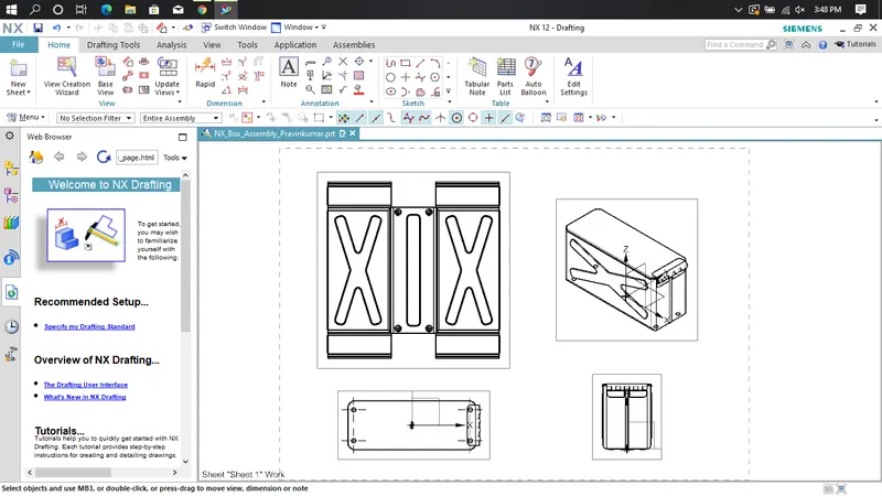
DRAFTING: It helps to create 2D drawing from a 3D model.
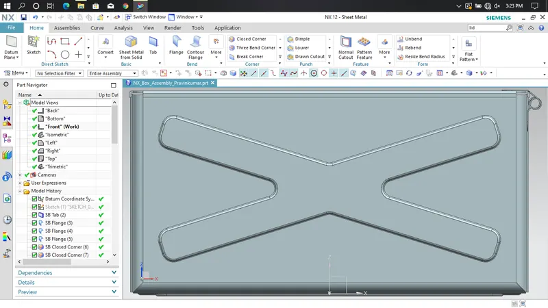
Front view:
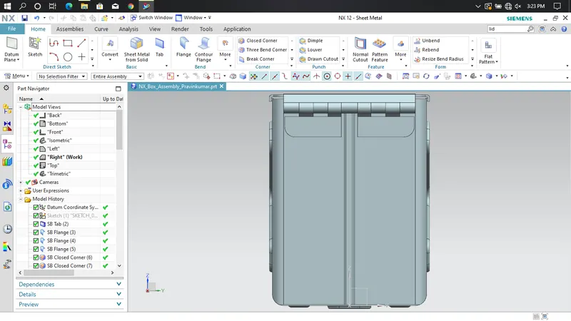
Side view:
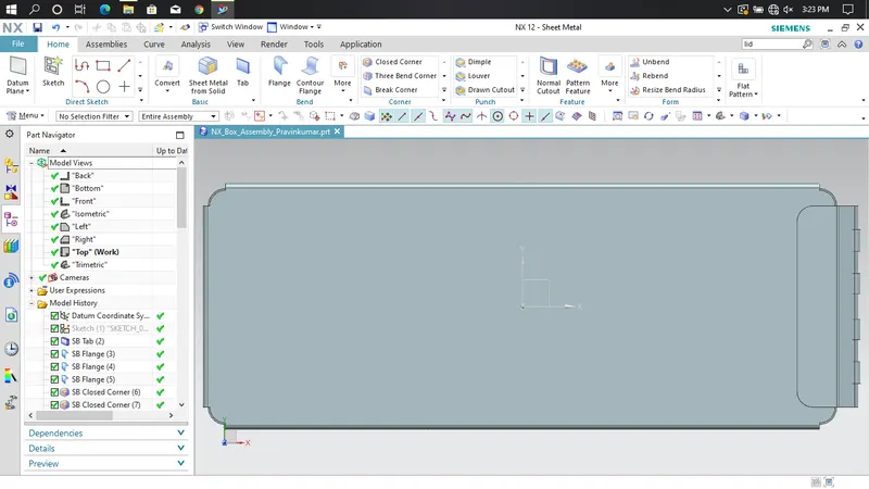
Top view:
Isometric view:
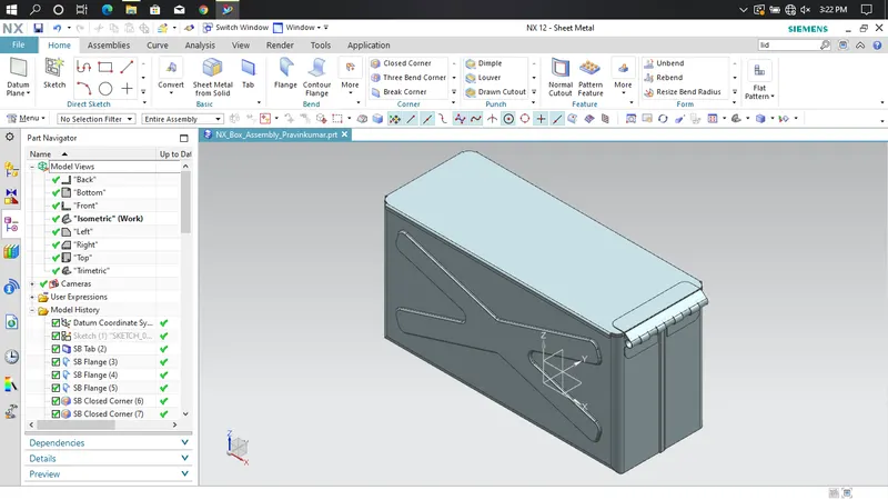
Bottom view:
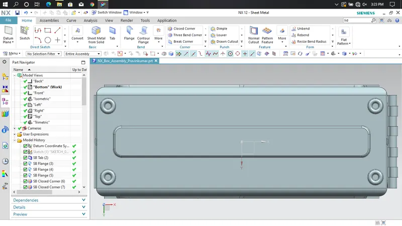
Detailed drawing sheet image:
Conclusion:
I have learned how to use features like tab, flange, break corner, closed corner, dimple, hem flange, bead, rebend, datum plane, flat pattern, mirror feature, mirror body, unite, normal cutout and unbend by creating a box assembly.