Advanced Sheet Metal Design Using NX Cad Challenge_1_Casing Design
CASING DESIGN IN ADVANCED SHEET METAL DESIGN USING NX CAD
Introduction:
The Sheet metal application provides an environment for the design of sheet metal parts used in Machinery, Automotive and Aerospace. Enclosures, Brackets and other parts are normally manufactured with break press. The sheet metal application are widely used in the,
- Aircraft Bodies
- Automobiles
- Utensils used for domestic purpose
- Beverage cans
In sheet metal application we can create a uniform thickness sheet metal parts using basic features such as flange, tabs and jogs. We can also do close corners, cutout and stiffening features. The complex sheet metal part can be designed in the solid model workbench and then we can convert into a sheet metal part. We can also import, clean up and convert a non-sheetmetal part into a valid sheet metal part. Flat pattern sheet metal data can be used for the manufacturing process. The material parameters such as thickness, bend radii and bend relief can be easily set as default settings.
Version used here is NX 12
Objective:
- To know about the required Design.
- To understand the Design parameters and the features to use for the design.
- To make the draft drawing of the part model.
Design Methodology:
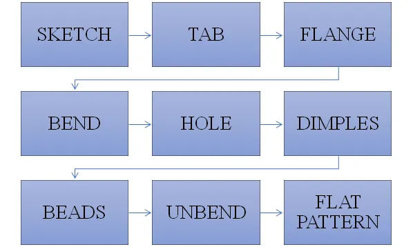
Description:
Tab: To create a base feature by extruding a sketch along a vector by a thickness value, or by adding material to existing faces and bend regions of a sheet metal part.
Flange: Flange command use to add a flat flange at an angle to a planar face and adds a bend between the two.
Normal cutout: To cut material by projecting a sketch onto the model and then cutting perpendicular to the faces intersected by the projection.
Break Corner: It is used to convert the sharp edges to the smooth edges of the corner.
Bend: Bend is used to create a bend in the flat body.
Hole: A Hole feature is used to create holes on the model.
Dimple: The Dimple command to lift an area of the model inside a sketch that simulates a stamping tool. A Dimple feature across cylindrical bends in the unbent state. An open or closed section type of the Dimple feature can be created across a bend and a planar face, or completely inside the bend.
Bead: It is used to create a conture shape according to the sketch in the required direction with required punch/die radius.
Mirror Feature: This is used to mirror a feature along a specific direction.
Unbend: It is used for bending corners of the unbend body.
Flat Pattern: Flat pattern is used to create flat pattern view which is used for drafting purposes.
Drafting: It helps to create 2D drawing from a 3D model.
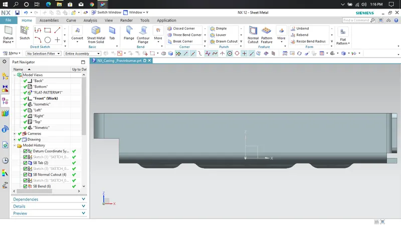
Front view:
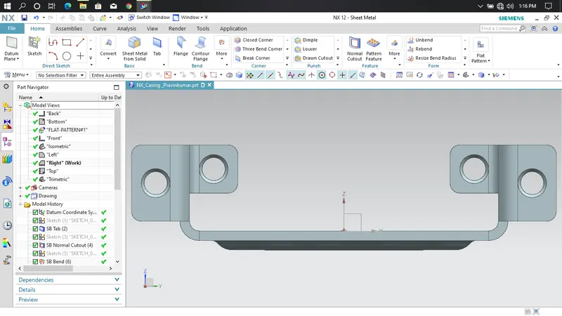
Side view:
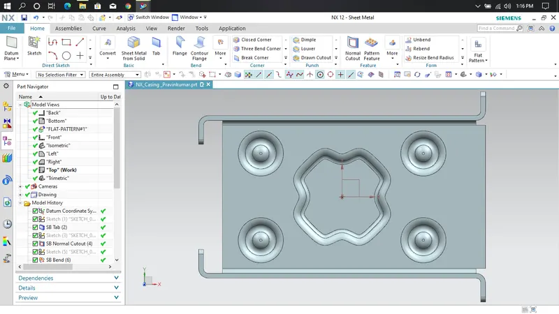
Top view:
Isometric view:

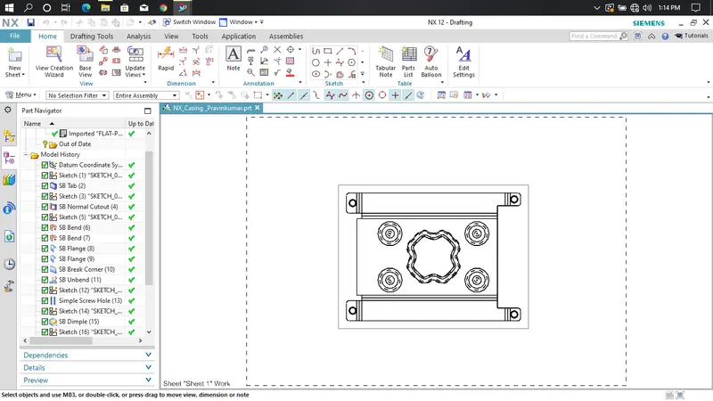
Detailed drawing sheet image:
Conclusion:
Thus, we have successfully designed sheet metal casing using NX Cad.